Sign In
Upload
Download
Table of Contents
Contents
Add to my manuals
Delete from my manuals
Share
URL of this page:
HTML Link:
Bookmark this page
Add
Manual will be automatically added to "My Manuals"
Print this page
×
Bookmark added
×
Added to my manuals
Manuals
Brands
Raymarine Manuals
Transducer
RVM-400 Series
Installation instructions manual
Raymarine RVM-400 Series Installation Instructions Manual
Hide thumbs
1
2
3
4
Table Of Contents
5
6
7
8
9
10
11
12
13
14
15
16
17
18
19
20
21
22
23
24
25
26
27
28
29
30
31
32
33
34
35
36
37
38
39
40
41
42
43
44
45
46
47
48
49
50
51
52
53
54
55
56
57
58
page
of
58
Go
/
58
Contents
Table of Contents
Troubleshooting
Bookmarks
Table of Contents
Table of Contents
Chapter 1 Important Information
Safety Warnings
Product Warnings
Regulatory Notices
Declaration of Conformity
Disclaimer
Warranty Registration
Product Disposal
IMO and SOLAS
Technical Accuracy
Publication Copyright
Chapter 2 Document Information
Applicable Products
Document Information
Product Documentation
Document Illustrations
Operation Instructions
Chapter 3 Product and System Overview
Product Overview
Realvision™ Max 3D Overview
Sonar Range
Compatible Sonar Modules and Displays
Realvision Transducer Extension Cables
Chapter 4 Parts Supplied
Parts Supplied - RVM-4Xx Series Transducers
Additional Parts Supplied
Chapter 5 Product Dimensions
Transducer Dimensions - RVM-4Xx
Realvision Transducer Cable Connector Dimensions
Chapter 6 Location Requirements
Warnings and Cautions
Location Requirements
Cored Fiberglass Hull Mounting
EMC Installation Guidelines
Chapter 7 Installation
Tools Required
Testing the Transducer
Transducer Mounting
Drilling Holes in the Hull
Assembling the External Components
Assembling the Internal Components
Finalizing the Installation
Anti-Fouling
Chapter 8 Cables and Connections - General Information
General Cabling Guidance
Cable Types and Length
Strain Relief
Cable Shielding
Chapter 9 Connections
Cable Routing
Connection
RVM-420 Connection
RVM-400 Connection
RVM-412 / RVM-420 Connection
Realvision Transducer Extension Cables
Making Connections
Chapter 10 System Checks and Troubleshooting
Realvision™ AHRS Calibration
Troubleshooting
Operation Instructions
Sonar Troubleshooting
Resetting the Sonar Module
Chapter 11 Maintenance
Routine Checks
Transducer Cleaning
Bridging Material Removal
Re-Applying Anti-Fouling Paint
Chapter 12 Technical Support
Raymarine Product Support and Servicing
Learning Resources
Chapter 13 Technical Specification
Physical Specification
Environmental Specification
Realvision™ Max 3D Sonar Specification
Sonar Range
Conformance Specification
Chapter 14 Spares and Accessories
Spares
Accessories
Advertisement
Quick Links
1
Chapter 6 Location Requirements
2
Location Requirements
3
Drilling Holes in the Hull
4
Transducer Mounting
Download this manual
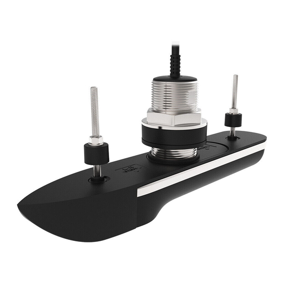
RVM-400 SERIES
THRU-HULL REALVISION™ MAX 3D SONAR TRANSDUCERS
INSTALLATION
INSTRUCTIONS
English (en-US)
Date:
01-2023
Document number:
87437 (Rev 1)
© 2023 Raymarine UK Limited
Table of
Contents
Previous
Page
Next
Page
1
2
3
4
5
Advertisement
Table of Contents
Troubleshooting
CHAPTER 10 SYSTEM CHECKS AND TROUBLESHOOTING
38
RealVision™ AHRS calibration
39
Sonar troubleshooting
40
Need help?
Do you have a question about the RVM-400 Series and is the answer not in the manual?
Ask a question
Questions and answers
Related Manuals for Raymarine RVM-400 Series
Transducer Raymarine RV-100 Installation Instructions Manual
Transom realvision 3d sonar transducer (46 pages)
Transducer Raymarine RV-100 RealVision 3D Installation Instructions Manual
Transom mount transducer (25 pages)
Transducer Raymarine RV-100 Installation Instructions
Hull / step bracket (2 pages)
Transducer Raymarine RV2 Series Installation Instructions
3d bronze thru-hull transducer (4 pages)
Transducer Raymarine Realvision RV-220P Installation Instructions Manual
3d bronze through-hull transducer (25 pages)
Transducer Raymarine REALVISION 3D Installation Instructions Manual
Stainless steel through-hull transducer (60 pages)
Transducer Raymarine RV-300 Series Installation Instructions Manual
Plastic thru-hull realvision 3d sonar transducers (50 pages)
Transducer Raymarine RVM-420 Installation Instructions Manual
(58 pages)
Transducer Raymarine RVM-100 Installation Instructions Manual
Transom realvision max 3d sonar transducers (56 pages)
Transducer Raymarine RSW-Wired Installation Instructions Manual
Smart performance wind transducer & gateway (74 pages)
Transducer Raymarine AUTOHELM ST50 PLUS DEPTH Operation And Installation
(23 pages)
Transducer Raymarine Wind Vane Service Manual
Short arm e22078/ long arm e22079 (12 pages)
Transducer Raymarine HYPERVISION HV-100 Installation Instructions Manual
(58 pages)
Transducer Raymarine Transducers User Manual
Transducers for fishfinders (56 pages)
Transducer Raymarine HYPERVISIONT HV-300 Series Installation Instructions Manual
(66 pages)
Transducer Raymarine HYPERVISION HV-300 Installation Instructions Manual
(64 pages)
This manual is also suitable for:
Rvm-412
Rvm-420
A80704
T70543
T70544
Table of Contents
Print
Rename the bookmark
Delete bookmark?
Delete from my manuals?
Login
Sign In
OR
Sign in with Facebook
Sign in with Google
Upload manual
Upload from disk
Upload from URL


Need help?
Do you have a question about the RVM-400 Series and is the answer not in the manual?
Questions and answers