Table of Contents
Advertisement
Quick Links
Applicable products
This document
is
applicable to
the
RV-2oo, RV-212(P/S), and
Rv-2zo(P/s)
Realvision" 3D bronze thru-hull transducers.
These transducers are capable of producing 3D sonar images when connected
to Realvision'.3D
variant
MFDS
running LightHouse'" 3 software.
Five
transducers are available
in
the
RV-2xx series, each having
the
same external shape and dimensions.
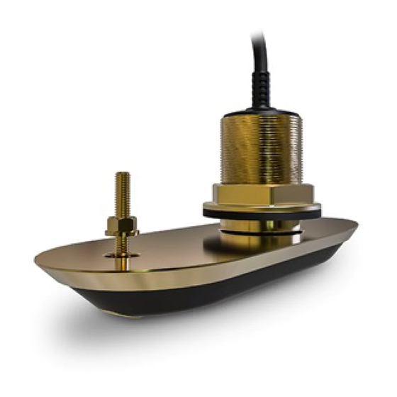
D'13799-1
splii-pair of
RV-212(P/5) or RV-220(P/S) transducers.
The hull geometry
of
your vessel determines
the
most appropriate transducers
to
use. You should fit transducers whose internal elements are matched to within
t6'
of
your
hull's
Model
no.
Part no.
Descripiion
Hull geometry
RV-200
A80465
Realvision'" 3D Bronze Thru-Hull Transducer,
0',
single
("all in
one")
Hull
with
O'(flat-bottom)
to 6'
deadrise angle.
RV-212P
480466
Realvision'" 3D Bronze Thru-Hull Transducer, 12', split-pair
Hull
with
6'to
18'
deadrise angle, port side
(pair
with A80467
below)
RV-212S
AAO467
Hull
with
6"
to'18' deadrise anqle, starboard side
(pair with
480466
above)
RV.22OP
A80468
Realvision" 3D Bronze Thru-Hull Transducer, 2O', split-pair
Hull with
14'to
26" deadrise angle, port side
(pair with
A80469
below)
RV-220S
A80469
Hull with
'14"
to
26" deadrise angle, starboard side
(pair
with
A8O468 above)
.
Bronze thru-hull transducers are recommended for fiberglass and
wooden
hulls and should not be used on a metal
hull.
.
Do NOT install bronze transducers on vessels
with
a positive ground system.
refer
to the
separate installation sheet.
Tools required
The
following tools
are required
to
install any of
the
transducers listed
under'Applicable
products".
6
75
mm / 3 inch
wrench
(spanner) or
suitable
size adjustable wrench (spanner)
7
Marine grade sealant (non-acetate based)
8
Adhesive
tape
Warning:
Transducer
operation
Only test and operate the transducer
in
the
water.
Do NOT operate
out
of water
as
overheating may
occur.
II
Warning: Marine-grade
sealant
Only
use marine-grade neutral cure
polyurethane
sealants. Do
NOT
use
sealants containing acetate or silicone,
which can cause damage
to
plastic pans.
Caution: Transducer cable
.
Do NOT use
the
transducer cable
to
lift or suspend
the
transducer; always
support
the transducer
body dlrectly
during installation.
.
Do NOT cut, shorten,
or
splice
the
transducer cable.
.
Do NOT remove
the
connector.
lf
the
cable
is
cut, it
cannot
be repaired.
Cutting the cable will
also
void the warranty.
Testing the transducer
Transducer
operation
should
be checked
before
installation.
1.
Connect the transducer to
the
multifunction display's
transducer connection.
2.
Fully submerge the transducer
in
water.
3.
Power up
the
display.
4.
Open
a
Fishfinder application on your display.
5.
lf required, select
the
relevant transducer/channel
from the Channel selection page
(Menurlicheiiilil).
6.
Check that accurate depth
and
temperature readings
are displayed.
7.
lt
you experience difficulties obtaining readings then
contact Raymarine Technical Support.
Multiple transducers
Note:
lf
you are installing
a
split-pair
of
transducers
(for
example, an RV-212P unit
with
an RV-212S
unit),
ensure that you
test
both transducers
together
by
connecting them to
the
multifunction display using
a
Y-cable and extension cable.
Refer
to the colored "Port" and "Starboard" labels
on
the
cables to ensure that you connect the transducer
cables to
the
correct Y-cable tails.
1
Power drill
2
62
mm
/
23/e
inch hole cutter
Drill bit (suitable
size
for drilling pilot holes)
4
9
mm
/
3/a
inch drill bit
(for drilling
anti-rotation
bolt
hole)
5
Half round file
Advertisement
Table of Contents


Need help?
Do you have a question about the RV2 Series and is the answer not in the manual?
Questions and answers