
Subscribe to Our Youtube Channel
Related Manuals for Raymarine HYPERVISION HV-100


Summary of Contents for Raymarine HYPERVISION HV-100
- Page 1 HYPERVISION HV-100 Installation instructions English (en-US) Date: 01-2019 Document number: 87362-1 © 2019 Raymarine UK Limited...
- Page 3 Software updates Check the Raymarine website for the latest software releases for your product. www.raymarine.com/software Product documentation The latest versions of all English and translated documents are available to download in PDF format from the website: www.raymarine.com/manuals.
-
Page 5: Table Of Contents
Contents Chapter 1 Important information..................7 Water ingress ..........................7 Disclaimer ............................7 Declaration of conformity......................8 Warranty registration ......................... 8 Product disposal ........................8 IMO and SOLAS ......................... 8 Technical accuracy ........................8 Chapter 2 Document and product information............. 9 2.1 Product documentation...................... 10 Operation instructions ...................... - Page 6 6.1 Routine checks ........................42 6.2 Transducer cleaning ......................43 6.3 Re-applying anti-fouling paint..................44 Chapter 7 Technical support..................45 7.1 Raymarine product support and servicing ..............46 7.2 Learning resources ......................48 Chapter 8 Technical specification................. 49 8.1 Technical specification ...................... 50 Physical specification......................
-
Page 7: Chapter 1 Important Information
Raymarine will not warrant products subjected to high-pressure washing. Disclaimer Raymarine does not warrant that this product is error-free or that it is compatible with products manufactured by any person or entity other than Raymarine. Important information... -
Page 8: Declaration Of Conformity
Raymarine is not responsible for damages or injuries caused by your use or inability to use the product, by the interaction of the product with products manufactured by others, or by errors in information utilized by the product supplied by third parties. -
Page 9: Chapter 2 Document And Product Information
Chapter 2: Document and product information Chapter contents • 2.1 Product documentation on page 10 • 2.2 Applicable products on page 11 • 2.3 Product overview on page 12 • 2.4 Required additional components on page 13 • 2.5 Parts supplied on page 14 Document and product information... -
Page 10: Product Documentation
Operation instructions For detailed operation instructions for your product, refer to the documentation that accompanies your display. All product documentation is available to download from the Raymarine website: www.raymarine.com/manuals. Document illustrations Your product and if applicable, its user interface may differ slightly from that shown in the illustrations in this document, depending on product variant and date of manufacture. -
Page 11: Applicable Products
2.2 Applicable products Part number Description A80603 HV-100 HyperVision™plastic transom mount transducer Document and product information... -
Page 12: Product Overview
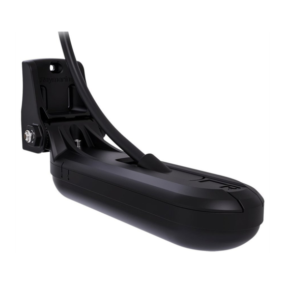
2.3 Product overview The HV-100 is a HyperVision™ transom mount plastic transducer. The transducer is compatible with HyperVision™ variant displays. HyperVision™ transducers are capable of producing sonar images for: • RealVision™ 3D (Hyper 1.2 MHz) • RealVision™ 3D (Standard 350 kHz) •... -
Page 13: Required Additional Components
2.4 Required additional components This product forms part of a system of electronics and requires the following additional components for full operation. • Compatible HyperVision™ sonar-capable device. Refer to Compatible displays , for a list of compatible products. • For longer cable runs, a transducer extension cable will also be required. Refer to HyperVision™... -
Page 14: Parts Supplied
2.5 Parts supplied The following parts are supplied with your product: Unpack your product carefully to prevent damage or loss of parts. Check the box contents against the list below. Retain the packaging and documentation for future reference. Transom bracket 3 x bracket fixing screws (4.2x19 mm A4 stainless steel) M5x10 hex bolt (A4 stainless steel) M5 washer (A4 stainless steel) -
Page 15: Chapter 3 Installation
Chapter 3: Installation Chapter contents • 3.1 Tools required on page 16 • 3.2 Pre-installation test on page 18 • 3.3 Selecting a location on page 19 • 3.4 Mounting on page 22 Installation... -
Page 16: Tools Required
3.1 Tools required The following tools are required to install your transducer: Power drill 2. 4 mm hex wrench (Allen key) 3. 5 mm hex wrench (Allen key) 4. Pozi-drive screw driver 5. Drill bit (suitable for pilot holes) 6. Marine grade sealant 24 mm (15/16 in) or suitable size hole cutter (only required when routing the cable through a bulkhead or transom) 8. -
Page 17: Anti-Fouling
Anti-fouling Where local regulations allow, it is recommended that you coat your transducer using a water-based anti-fouling paint. This will help prevent the build-up of organic growth, which can reduce transducer performance. Important: • Before applying water-based anti-fouling paint, check that local environmental rules and regulations do not prohibit the use of anti-fouling paint. -
Page 18: Pre-Installation Test
> Transducer). 6. Check that accurate depth and temperature readings are displayed. 7. If you experience difficulties obtaining readings then contact Raymarine Technical Support. Warning: Transducer operation Only test and operate the transducer in the water. Do NOT operate out of water as overheating may occur. -
Page 19: Selecting A Location
3.3 Selecting a location Warnings and cautions Important: Before proceeding, ensure that you have read and understood the warnings and cautions provided in the Chapter 1 Important information section of this document. Location requirements The guidelines below should be followed when selecting a location for the transducer. Note: The transducer is not suitable for mounting on vessels where the transom is aft of the propeller(s). -
Page 20: Emc Installation Guidelines
EMC installation guidelines Raymarine equipment and accessories conform to the appropriate Electromagnetic Compatibility (EMC) regulations, to minimize electromagnetic interference between equipment and minimize the effect such interference could have on the performance of your system Correct installation is required to ensure that EMC performance is not compromised. - Page 21 Transducer cable length: 6 m (19.69 ft). 130.00 mm (5.12 in) 84.00 mm (3.31 in) 22.20 mm (0.87 in) Installation...
-
Page 22: Mounting
3.4 Mounting Transducer assembly Follow the steps below to assemble the transducer ready for attaching to the Transom bracket. 1. Slide the hanger bracket over the top of the transducer until the notch in the side of the bracket hanger aligns with the unlocked symbol on the side of the transducer. 2. -
Page 23: Mounting The Transom Bracket
Ensure tightening torque does not exceed 2 Nm (1.48 ft lb). Overtightening may cause damage to the transducer. Mounting the transom bracket The transducer must be mounted on the transom using the parts provided. The steps below describe the initial mounting steps required in order to test your transducer’s performance. After testing the transducer you must finish the mounting using the instructions in the Finishing the transducer mounting... -
Page 24: Mounting The Transducer Assembly
6. Using a pozi-drive screw driver and the screws provided, secure the transom bracket using the adjustment slots. Note: The third locking screw is not used until the transducer has been successfully tested. Mounting the transducer assembly Important: • Only perform the installation with your vessel out of the water. •... -
Page 25: Mounting The Escutcheon Plate
2. Slide the M6 metal washer over the M6 hex (Allen) bolt. 3. Slide the supplied M6 hex (Allen) bolt through the transom bracket hole. 4. Place the M6 locking nut into the captive area on the mounting bracket and hold in position. 5. -
Page 26: Testing And Adjusting The Transducer
Note: To avoid possible damage to the transducer cable, use a file to round-off the edges of the hole that the cable passes through. Testing and adjusting the transducer Once the initial mounting procedures have been carried out, the transducer must be tested before locking the transducer’s position. - Page 27 i. Loosen the mounting bolt to adjust the transducer angle. Angle adjustment ii. Loosen the 2 mounting bracket screws to adjust the transducer height. Height adjustment iii. Re-tighten the mounting bolt and mounting screws before re-testing. Note: • It may be necessary to make several adjustments to the transducer before obtaining optimum performance.
-
Page 28: Finalizing The Transducer Mounting
Finalizing the transducer mounting Once you have achieved optimum performance at the desired vessel speeds the transducer must be locked into position to complete the installation. 1. Drill the locking hole location taking care not to damage the transom bracket. 2. - Page 29 The anti-fouling paint should be applied in a thin and even coat covering all externally exposed transducer surfaces. You should clean your transducer regularly and re-apply anti-fouling paint every 6 months, or sooner depending on how rapidly organic growth builds up. Refer to 6.2 Transducer cleaning for cleaning guidance.
-
Page 31: Chapter 4 Connections
Chapter 4: Connections Chapter contents • 4.1 General cabling guidance on page 32 • 4.2 Cable routing on page 33 • 4.3 Making connections on page 34 Connections... -
Page 32: General Cabling Guidance
• Unless otherwise stated use only standard cables of the correct type, supplied by Raymarine. • Ensure that any non-Raymarine cables are of the correct quality and gauge. For example, longer power cable runs may require larger wire gauges to minimize voltage drop along the run. -
Page 33: Cable Routing
4.2 Cable routing Cable routing requirements for the transducer cable. Important: To avoid interference, the cable must be routed as far away from VHF radio antenna devices and cables as possible. • Check that the cable is long enough to reach the display it will be connected to. Optional extension cables are available, if required. -
Page 34: Making Connections
4.3 Making connections Follow the steps below to connect the cable(s) to your product. 1. Ensure that the vessel's power supply is switched off. 2. Ensure that the device being connected to the unit has been installed in accordance with the installation instructions supplied with that device. -
Page 35: Chapter 5 System Checks And Troubleshooting
Chapter 5: System checks and troubleshooting Chapter contents • 5.1 Operation instructions on page 36 • 5.2 Troubleshooting on page 37 System checks and troubleshooting... -
Page 36: Operation Instructions
5.1 Operation instructions For detailed operation instructions for your product, refer to the documentation that accompanies your display. All product documentation is available to download from the Raymarine website: www.raymarine.com/manuals. -
Page 37: Troubleshooting
If after referring to this section you are still having problems with your product, please refer to the Technical support section of this manual for useful links and Raymarine Product Support contact details. - Page 38 Possible causes Possible solutions Power source insufficient With the product under load, using a multi-meter, check the power supply voltage as close to the unit as possible to establish actual voltage when the current is flowing. (Check your product’s Technical specification for power supply requirements.) Damaged or fouled Check transducer condition, ensuring it is not damaged and is free transducer...
-
Page 39: Resetting The Sonar
Possible causes Possible solutions can cause the Fishfinder applications to stop scrolling or the unit to reset/turn off), replace if necessary. Transducer location • Check that the transducer has been installed in accordance with the instructions provided with the transducer. •... -
Page 41: Chapter 6 Maintenance
Chapter 6: Maintenance Chapter contents • 6.1 Routine checks on page 42 • 6.2 Transducer cleaning on page 43 • 6.3 Re-applying anti-fouling paint on page 44 Maintenance... -
Page 42: Routine Checks
6.1 Routine checks The following periodic checks should be made: • Examine cables for signs of damage, such as chafing, cuts or nicks. • Check that the cable connectors are firmly attached and that their locking mechanisms are properly engaged. Note: Cable checks should be carried out with the power supply switched off. -
Page 43: Transducer Cleaning
6.2 Transducer cleaning You must clean your transducer regularly to remove organic growth. Organic growth can build up quickly on the bottom face of your transducer; this can impact transducer performance in a matter of weeks. Important: • When cleaning growth from an anti-fouled transducer, take care not to let paint dust and other debris enter the water, as this can have an impact on aquatic life. -
Page 44: Re-Applying Anti-Fouling Paint
6.3 Re-applying anti-fouling paint If you have applied anti-fouling paint to your transducer, it is important to re-apply it at least every 6 months, to maintain effectiveness. Follow the instructions below to re-apply anti-fouling paint. Important: • Following environmental best practice, preparation and re-application of the anti-fouling paint should be performed using suitable washdown facilities, which ensures paint particles do not enter the water and impact aquatic life. -
Page 45: Chapter 7 Technical Support
Chapter 7: Technical support Chapter contents • 7.1 Raymarine product support and servicing on page 46 • 7.2 Learning resources on page 48 Technical support... -
Page 46: Raymarine Product Support And Servicing
You can obtain this product information using diagnostic pages of the connected MFD. Servicing and warranty Raymarine offers dedicated service departments for warranty, service, and repairs. Don’t forget to visit the Raymarine website to register your product for extended warranty benefits: http://www.raymarine.co.uk/display/?id=788. Region Contact •... - Page 47 • Tel: +358 (0)207 619 937 Norway • E-Mail: support.no@raymarine.com (Raymarine subsidiary) • Tel: +47 692 64 600 Denmark • E-Mail: support.dk@raymarine.com (Raymarine subsidiary) • Tel: +45 437 164 64 Russia • E-Mail: info@mikstmarine.ru (Authorized Raymarine distributor) • Tel: +7 495 788 0508 Technical support...
-
Page 48: Learning Resources
7.2 Learning resources Raymarine has produced a range of learning resources to help you get the most out of your products. Video tutorials Raymarine official channel on YouTube: • http://www.youtube.com/user/RaymarineInc LightHouse™ 3 tips and tricks: • http://www.raymarine.com/multifunction-displays/light- house3/tips-and-tricks Video Gallery: •... -
Page 49: Chapter 8 Technical Specification
Chapter 8: Technical specification Chapter contents • 8.1 Technical specification on page 50 Technical specification... -
Page 50: Technical Specification
8.1 Technical specification Physical specification Overall dimensions: • Length: 224.99 mm (8.86 in) • Height: 112.69 mm (4.44 in) • Width: 76.00 mm (2.99 in) Cable length: • HV-100: 6 m (19.69 ft) fitted cable Weight (unboxed): 1.05 kg (2.31 lb) Environmental specification –2ºC (28.4ºF) to + 55ºC (131ºF) Operating temperature... -
Page 51: Chapter 9 Spares And Accessories
Chapter 9: Spares and accessories Chapter contents • 9.1 Spares on page 52 • 9.2 Accessories on page 53 Spares and accessories... -
Page 52: Spares
9.1 Spares Description Part number HV-100 Transom bracket R70651... -
Page 53: Accessories
9.2 Accessories Description Part number HV-100 trolling motor mount A80557 HyperVision™ transducer extension cable 4 m A80562 (13.12 ft) Spares and accessories... - Page 55 Index Operation instructions ........10, 36 Accessories ............52–53 Anti-fouling ........... 17, 28, 44 Assembly ..............22 Product recycling (WEEE) .......... 8 Product support............46 Cable extension ............33 Cable protection............32 Service Center............46 Cable routing............33 Servicing..............7 Cleaning the transducer .......... 43 Strain relief, Cable protection Connections...
- Page 58 Raymarine Marine House, Cartwright Drive, Fareham, Hampshire. PO15 5RJ. United Kingdom. Tel: +44 (0)1329 246 700 www.raymarine.com a brand by...
Need help?
Do you have a question about the HYPERVISION HV-100 and is the answer not in the manual?
Questions and answers