
Related Manuals for Raymarine RVM-100


Summary of Contents for Raymarine RVM-100
- Page 1 RVM-100 TRANSOM REALVISION™ MAX 3D SONAR TRANSDUCERS INSTALLATION INSTRUCTIONS English (en-US) Date: 01-2023 Document number: 87432 (Rev 1) © 2023 Raymarine UK Limited...
- Page 3 Trademark and patents notice Raymarine, Tacktick, Clear Pulse, Truzoom, SeaTalk , SeaTalk , SeaTalkng , and Micronet, are registered or claimed trademarks of Raymarine Belgium. FLIR, YachtSense , DockSense, LightHouse, RangeFusion, DownVision, SideVision, RealVision, HyperVision, Dragonfly, Element, Quantum, Axiom, Instalert, Infrared Everywhere, The World’s Sixth Sense and ClearCruise are registered or claimed trademarks of FLIR Systems, Inc.
-
Page 5: Table Of Contents
CONTENTS CHAPTER 1 IMPORTANT INFORMATION ......7 Parts supplied ..............16 Safety warnings ................7 CHAPTER 5 PRODUCT DIMENSIONS........17 Product warnings ............... 7 Transducer dimensions ........... 18 Regulatory notices ..............8 RealVision transducer cable connector Declaration of Conformity dimensions ................. 18 ..........8 Disclaimer ................8... - Page 6 CHAPTER 11 MAINTENANCE ..........43 Routine checks 11.1 ..............44 Transducer cleaning 11.2 ............44 Re-applying anti-fouling paint 11.3 ........44 CHAPTER 12 TECHNICAL SUPPORT........45 Raymarine product support and servicing 12.1 ....46 Learning resources 12.2 ............47 CHAPTER 13 TECHNICAL SPECIFICATION ....... 48 Physical specification 13.1 ............49...
-
Page 7: Chapter 1 Important Information
Caution: Service and maintenance This product contains no user serviceable components. Please Warning: Transducer cables refer all maintenance and repair to authorized Raymarine Do not remove the transducer cable whilst the product is dealers. Unauthorized repair may affect your warranty. -
Page 8: Regulatory Notices
Disclaimer leisure marine boats and workboats NOT covered by International Maritime Raymarine does not warrant that this product is error-free or that it is Organization (IMO) and Safety of Life at Sea (SOLAS) Carriage Regulations. compatible with products manufactured by any person or entity other than Raymarine. -
Page 9: Publication Copyright
Publication copyright Copyright ©2023 Raymarine UK Ltd. All rights reserved. No parts of this material may be copied, translated, or transmitted (in any medium) without the prior written permission of Raymarine UK Ltd. Important information... -
Page 10: Chapter 2 Document Information
CHAPTER 2: DOCUMENT INFORMATION CHAPTER CONTENTS • 2.1 Applicable products — page 11 • 2.2 Document information — page 11 • 2.3 Product documentation — page 11... -
Page 11: Applicable Products
2.1 Applicable products • 87305 — RV-100 / RVM-100 Hull / Step Bracket Installation Instructions. • 87306 — RV-100 / RVM-100 Jack Plate Mount and Spacer Kit Installation This document is applicable to the following products: Instructions. • RVM-100 RealVision™ Max 3D Plastic transom mount transducer, part number A80703. -
Page 12: Chapter 3 Product And System Overview
CHAPTER 3: PRODUCT AND SYSTEM OVERVIEW CHAPTER CONTENTS • 3.1 Product overview — page 13... -
Page 13: Product Overview
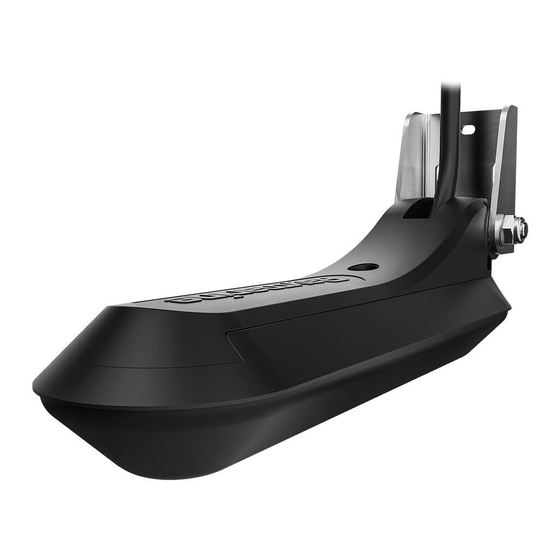
3.1 Product overview – Step mount bracket (part number A80479). – Trolling motor mount (part number: A80483). The RVM-100 transducer is a transom mount RealVision™ Max 3D transducer, – Jack plate mount (part number A80480). with plastic construction. – Jack plate spacer kit (part number A80482). -
Page 14: Sonar Range
• Only use Raymarine® transducer extension cables. Sonar channel Range Raymarine® offers he following optional extension cables are available: CHIRP sonar: 0.6 m (2 ft) to 366 m (1,200 ft) • RealVision™ transducer extension cable 3 m (9.8 ft) (part number A80475) DownVision™:... -
Page 15: Chapter 4 Parts Supplied
CHAPTER 4: PARTS SUPPLIED CHAPTER CONTENTS • 4.1 Parts supplied — page 16 Parts supplied... -
Page 16: Parts Supplied
4.1 Parts supplied Item Description Cable connector kit, consisting of: The following parts are supplied in the box. • O Ring Unpack your product carefully to prevent damage or loss of parts. Check the box contents against the list below. Retain the packaging and documentation •... -
Page 17: Chapter 5 Product Dimensions
CHAPTER 5: PRODUCT DIMENSIONS CHAPTER CONTENTS • 5.1 Transducer dimensions — page 18 • 5.2 RealVision transducer cable connector dimensions — page 18 Product dimensions... -
Page 18: Transducer Dimensions
5.1 Transducer dimensions 5.2 RealVision transducer cable connector dimensions The dimensions of the transducer cable and cable connector are shown below. Cable connector dimensions Item Dimension Item Dimension 32.00 mm (1.26 in) 76.00 mm (3.00 in) 25.00 mm (1.00 in) 120.00 mm (4.72 in) 96.00 mm (3.80 in) 256.6 mm (10.10 in) - Page 19 Note: For installations where space behind the display is limited, a right-angled transducer cable adaptor is available (A80515). Using the right angled cable adaptor will reduce dimension E above by 20 mm (0.79 in.) Product dimensions...
-
Page 20: Chapter 6 Location Requirements
CHAPTER 6: LOCATION REQUIREMENTS CHAPTER CONTENTS • 6.1 Location requirements — page 21 • 6.2 Transducer angle requirements — page 22 • 6.3 EMC installation guidelines — page 22... -
Page 21: Location Requirements
6.1 Location requirements The guidelines below should be followed when selecting a location for the transducer. Note: Optimum transducer location will vary depending on vessel type. Optimum transducer height and angle should be obtained by testing the transducer Note: The illustration above provides potential transducer locations for with the vessel in the water. -
Page 22: Transducer Angle Requirements
For optimum EMC performance we recommend that wherever possible: • Raymarine® equipment and cables connected to it are: – At least 1 m (3.3 ft) from any equipment transmitting or cables carrying radio signals e.g. - Page 23 Note: Where constraints on the installation prevent any of the above recommendations, always ensure the maximum possible separation between different items of electrical equipment, to provide the best conditions for EMC performance throughout the installation. Location requirements...
-
Page 24: Chapter 7 Installation
CHAPTER 7: INSTALLATION CHAPTER CONTENTS • 7.1 Warnings and cautions — page 25 • 7.2 Tools required — page 25 • 7.3 Pre-installation test — page 26 • 7.4 Transducer cable routing guidance — page 26 • 7.5 Mounting — page 27 •... -
Page 25: Warnings And Cautions
7.1 Warnings and cautions 5. Marine-grade neutral cure polyurethane sealant (non-acetate and non-silicone based) Important: 6. 25 mm (1 inch) Hole saw (only required if you are routing the cable through the transom and / or a bulkhead.) Before proceeding, ensure that you have read and understood the warnings and cautions provided in the following section of this document: Masking or Adhesive tape (Used to fix the mounting template to the p.7 —... -
Page 26: Pre-Installation Test
([Menu > All channels]). 7. Check that accurate depth and where applicable temperature readings are displayed. 8. If you experience difficulties obtaining readings then contact Raymarine Technical Support. The anti-fouling paint should be applied in a thin and even coat covering all externally exposed transducer surfaces. -
Page 27: Realvision Transducer Extension Cables
• Only use Raymarine® transducer extension cables. 3. Drill 2 x holes for the adjustment slot screws as indicated on the template. Raymarine® offers he following optional extension cables are available: • RealVision™ transducer extension cable 3 m (9.8 ft) (part number A80475) •... -
Page 28: Mounting The Transducer
4. Using a pozi-drive screw driver and the screws provided, secure the Note: transom mount bracket using the 2 adjustment slots. The screw located on top of the transducer is used when connecting the transducer to a mounting adaptor such as the Step mount bracket (A80479). You do not need to adjust this screw for transom mount installations. -
Page 29: Routing The Cable
6. Tighten the nut onto the mounting bolt, using 2 x 14 mm wrenches or 7. Where applicable, cover the hole in the transom using the supplied adjustable wrenches, until the transducer is secure, but can still be escutcheon plate. adjusted (tilted) by hand. -
Page 30: Testing And Adjusting The Transducer
7.6 Testing and adjusting the transducer 7. Pull the cable so that it is tight, ready for the next cable clip. 8. Repeat steps 2 to 7 for all cable clips. After the initial installation has been carried out, the transducer should be Mounting the escutcheon plate tested and —... -
Page 31: Finalizing The Transducer Mounting
7.7 Finalizing the transducer mounting Angle adjustment After making any necessary adjustments to achieve optimum performance for your vessel, the transducer installation must be finalized by locking the transducer’s position. Note: After you apply marine grade sealant, always allow time for the sealant to fully cure before returning your vessel to the water. -
Page 32: Anti-Fouling
7. Fully tighten the nut and bolt. You should clean your transducer regularly and re-apply anti-fouling paint every 6 months, or sooner depending on how rapidly organic growth builds Do not exceed a torque of 35 N·m (25.8 lbf·ft). The transducer should not be easily moveable by hand, and should remain in its normal operating For guidance on transducer cleaning refer to p.44 —... -
Page 33: Chapter 8 Cables And Connections - General Information
CHAPTER 8: CABLES AND CONNECTIONS — GENERAL INFORMATION CHAPTER CONTENTS • 8.1 General cabling guidance — page 34 Cables and connections — General information... -
Page 34: General Cabling Guidance
It is important to use cables of the appropriate type and length. • Unless otherwise stated only use cables supplied by Raymarine. • Where it is necessary to use non-Raymarine cables, ensure that they are of correct quality and gauge for their intended purpose. (e.g.: longer power cable runs may require larger wire gauges to minimize voltage drop along the run). -
Page 35: Chapter 9 Connections
CHAPTER 9: CONNECTIONS CHAPTER CONTENTS • 9.1 Attaching the connector locking collar — page 36 • 9.2 Connecting the transducer — page 37 • 9.3 RealVision transducer extension cables — page 37 • 9.4 Maximum transducer cable length — page 37 Connections... -
Page 36: Attaching The Connector Locking Collar
9.1 Attaching the connector locking collar locking collar (labelled ‘A’ in the illustration), are closest to the plug-end of the connector. The supplied cable is provided with a separate locking collar assembly, 2. Slide the split-ring over the end of the connector, then push it towards the ensuring that the cable connection is secure. -
Page 37: Connecting The Transducer
• For best performance, cable runs should be kept to a minimum. • Only use Raymarine® transducer extension cables. Raymarine® offers he following optional extension cables are available: • RealVision™ transducer extension cable 3 m (9.8 ft) (part number A80475) •... -
Page 38: Chapter 10 System Checks And Troubleshooting
CHAPTER 10: SYSTEM CHECKS AND TROUBLESHOOTING CHAPTER CONTENTS • 10.1 RealVision™ AHRS calibration — page 39 • 10.2 Troubleshooting — page 39... -
Page 39: Realvision™ Ahrs Calibration
Before packing and shipping, all Raymarine® products are subjected to comprehensive testing and quality assurance programs. If you do experience Calibration is an automatic process and starts after your vessel has turned problems with your product, this section will help you to diagnose and correct approximately 100°... - Page 40 2. Check the power supply cable and connectors corrosion, replace if necessary. for signs of damage or corrosion, replace if External sonar Ensure all Raymarine® products contain the necessary. module: software latest available software, check the Raymarine® 3. With the unit turned on, try flexing the cable...
- Page 41 Poor / problematic image Possible causes Possible solutions Damaged cables Check the unit’s connector for broken or bent Possible causes Possible solutions pins. Targets will appear Increase vessel speed. differently if your 2. Check that the cable connector is fully inserted vessel is stationary into the unit and that the locking collar is in the (e.g.: fish will appear...
-
Page 42: Resetting The Sonar Module
Resetting the sonar module You can use the reset function on a compatible Raymarine multifunction display to restore the sonar module to its factory default settings. In the fishfinder application:... -
Page 43: Chapter 11 Maintenance
CHAPTER 11: MAINTENANCE CHAPTER CONTENTS • 11.1 Routine checks — page 44 • 11.2 Transducer cleaning — page 44 • 11.3 Re-applying anti-fouling paint — page 44 Maintenance... -
Page 44: Routine Checks
11.1 Routine checks • Use a scouring pad, such as a green Scotch Brite™ pad and a mild household cleaning detergent to clean moderate growth build up. The following periodic checks should be made: • You may need to use a fine grade wet and dry paper and a mild household cleaning detergent to clean severe build up. -
Page 45: Chapter 12 Technical Support
CHAPTER 12: TECHNICAL SUPPORT CHAPTER CONTENTS • 12.1 Raymarine product support and servicing — page 46 • 12.2 Learning resources — page 47 Technical support... -
Page 46: Raymarine Product Support And Servicing
Raymarine offers dedicated service departments for warranty, service, and • E-Mail: support.it@raymarine.com repairs. • Tel: +39 02 9945 1001 Don’t forget to visit the Raymarine website to register your product for Spain (Authorized Raymarine distributor): extended warranty benefits: http://www.raymarine.co.uk/display/?id=788. • E-Mail: sat@azimut.es United Kingdom (UK), EMEA, and Asia Pacific: •... -
Page 47: Learning Resources
Russia (Authorized Raymarine distributor): • E-Mail: info@mikstmarine.ru • Tel: +7 495 788 0508 12.2 Learning resources Raymarine has produced a range of learning resources to help you get the most out of your products. Video tutorials Raymarine official channel on YouTube •... -
Page 48: Chapter 13 Technical Specification
CHAPTER 13: TECHNICAL SPECIFICATION CHAPTER CONTENTS • 13.1 Physical specification — page 49 • 13.2 Environmental specification — page 49 • 13.3 RealVision™ Max 3D sonar specification — page 49 • 13.4 Conformance specification — page 49... -
Page 49: Physical Specification
13.1 Physical specification Sonar range The sonar range is the effective depth or distance that the transducer can Specification operate to, in optimum weather conditions. Dimensions (including bracket): • Length: 256.6 mm (10.10 in) The following ranges apply to RealVision™ Max 3D sonar channels: •... -
Page 50: Chapter 14 Spares And Accessories
CHAPTER 14: SPARES AND ACCESSORIES CHAPTER CONTENTS • 14.1 Accessories — page 51... -
Page 51: Accessories
14.1 Accessories Extension cables and adapters • A80515 — RealVision™ transducer right-angled adapter cable 400 mm (15.7 in.). • A80475 — RealVision™ transducer extension cable 3 m (11.8 ft.). • A80476 — RealVision™ transducer extension cable 5 m (19.7 ft.). •... - Page 53 Index Electromagnetic Compatibility..............22 EMC, See Electromagnetic Compatibility Escutcheon plate..................30 Accessories ....................51 Anti-fouling .................. 25, 32, 44 Applicable documents................11 Finalizing mounting .................. 31 Bracket mounting ..................27 Installation angle ....................22 Cable bend radius ................18 Cable length ..................18 Cable Testing ...................26, 30 Protection ....................
- Page 54 Product recycling (WEEE) ................8 Product support..................46 Related documents ...................11 Routine checks ..................44 Routing the cable ..................29 Securing the cable .................. 29 Service Center..................46 Servicing....................7 Sonar channels..................13 Sonar modules ..................14 Sonar range..................14, 49 Step mount bracket ..................
- Page 56 Raymarine (UK / EU) Marine House, Cartwright Drive, Fareham, Hampshire. PO15 5RJ. United Kingdom. Tel: (+44) (0)1329 246 700 www.raymarine.co.uk Raymarine (US) 110 Lowell Road, Hudson, NH 03051. United States of America. Tel: (+1) 603-324-7900 www.raymarine.com...
Need help?
Do you have a question about the RVM-100 and is the answer not in the manual?
Questions and answers