
Related Manuals for Raymarine DownVision CPT-70


Summary of Contents for Raymarine DownVision CPT-70
- Page 1 T h r u -H u ll Tr a n s d u c e r s CPT -70 / CPT -80 / CPT -110 / CPT -120 Installation instructions Date: 05-2015 Document number: 87201-2-EN © 2015 Raymarine UK Limited...
- Page 3 Trademark and patents notice Raymarine, Tacktick, Clear Pulse, Truzoom, HSB, SeaTalk, SeaTalk , SeaTalk , Micronet, Raytech, Gear Up, Marine Shield, Seahawk, Autohelm, Automagic, and Visionality are registered or claimed trademarks of Raymarine Belgium. FLIR, DownVision, SideVision, Dragonfly, Instalert, Infrared Everywhere, and The World’s Sixth Sense are registered or claimed trademarks of FLIR Systems, Inc.
-
Page 5: Table Of Contents
Contents Chapter 1 Important information......7 Chapter 10 Technical support ......43 Certified Installation ........... 7 10.1 Raymarine customer support ......44 Transducer cleaning ..........7 10.2 Viewing product information ........ 44 Water ingress ............7 Chapter 11 Technical specification....45 Disclaimer .............. - Page 6 CPT-70 / CPT-80 / CPT-110 / CPT-120...
-
Page 7: Chapter 1 Important Information
Raymarine approved installer. A certified installation qualifies for enhanced product warranty benefits. • Cutting the transducer cable will Contact your Raymarine dealer for further details, void the warranty and invalidate the and refer to the separate warranty document packed European CE mark. -
Page 8: Disclaimer
Disclaimer check the Raymarine website (www.raymarine.com) to ensure you have the most up-to-date version(s) of Raymarine does not warrant that this product is the documentation for your product. error-free or that it is compatible with products manufactured by any person or entity other than Raymarine. -
Page 9: Chapter 2 Document And Product Information
Chapter 2: Document and product information Chapter contents • 2.1 Document information on page 10 • 2.2 CHIRP Sonar overview on page 11 • 2.3 CHIRP DownVision overview on page 11 Document and product information... -
Page 10: Document Information
This document contains important information should not be used on a wooden hull. related to the installation of your Raymarine product. Document illustrations The document includes information to help you: Your product may differ slightly from that shown •... -
Page 11: Chirp Sonar Overview
2.2 CHIRP Sonar overview 2.3 CHIRP DownVision overview CHIRP sonar produces a conical shaped beam, the DownVision produces a wide–angle side-to-side coverage of the conical beam is the water column beam and a thin fore-to-aft beam. The coverage of directly beneath the vessel the DownVision beam is a water column directly beneath and to the sides of the vessel. - Page 12 CPT-70 / CPT-80 / CPT-110 / CPT-120...
-
Page 13: Chapter 3 Planning The Installation
Chapter 3: Planning the installation Chapter contents • 3.1 Installation checklist on page 14 • 3.2 Parts supplied on page 14 • 3.3 Required additional components on page 15 • 3.4 Compatible DownVision products on page 15 • 3.5 Tools required on page 16 •... -
Page 14: Installation Checklist
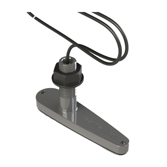
3.1 Installation checklist 3.2 Parts supplied Installation includes the following activities: Parts supplied — CPT-70 / CPT-110 Installation Task Plan your system. Obtain all required equipment and tools. Site all equipment. Route all cables. Drill cable and mounting holes. Make all connections into equipment. D12966-2 Thru-hull plastic transducer Secure all equipment in place. -
Page 15: Required Additional Components
3.3 Required additional components 3.4 Compatible DownVision products This product forms part of a system of electronics and requires the following additional components for The transducer can be connected directly to the full operation. following DownVision sonar modules and displays. •... -
Page 16: Tools Required
Raymarine accepts no liability for damage caused due to the use of unsuitable materials. CPT-70 / CPT-80 / CPT-110 / CPT-120... -
Page 17: Location Requirements
3.7 Location requirements Step The guidelines below should be followed when selecting a location for your transducer. Row of rivets For best performance the transducer should be Strake installed in a location with the least turbulence and aeration. • The transducer must be installed in the correct orientation, as identified on the deadrise / fairing Important: Do NOT install the transducer in-line block. -
Page 18: Product Dimensions
3.8 Product dimensions CPT-70 / CPT-110 plastic transducer dimensions Transducer only 32 mm (1.26 in) 75.5 mm (2.97 in) 30 mm (1.18 in) 25 mm (0.98 in) 210.8 mm (8.3 in) 52 mm (2 in) D12965-2 Transducer with dead rise block 32 mm (1.26 in) 68.5 mm (2.7 in) -
Page 19: Chapter 4 Cables And Connections
Chapter 4: Cables and connections Chapter contents • 4.1 General cabling guidance on page 20 • 4.2 Cable routing on page 20 • 4.3 Connections overview on page 21 • 4.4 Transducer cable connection on page 22 Cables and connections... -
Page 20: General Cabling Guidance
Raymarine. • Use grommets in any pass through holes to • Ensure that any non-Raymarine cables are of the prevent damage to the transducer cable. correct quality and gauge. For example, longer •... -
Page 21: Connections Overview
4.3 Connections overview Unit / Compatible Connector Description Display transducer Use the following information to help you identify the Yellow – 3 • DV • CPT-DV connections on your product. keyway • Wi-Fish Connector Connector type Connects to: CPT-60 / Dragonfly display CPT-70 / CPT–80... -
Page 22: Transducer Cable Connection
Current Dragonfly-6, Dragonfly-7 displays and CPT-60 / CPT-70 / CPT-80 transducer designs have • Raymarine recommends a maximum of one cable been modified to include the improved 3 keyway extension for any single transducer cable. -
Page 23: Chapter 5 Pre-Installation Test
Chapter 5: Pre-installation test Chapter contents • 5.1 Testing the transducer on page 24 Pre-installation test... -
Page 24: Testing The Transducer
5. Check that accurate depth and temperature readings are displayed. 6. If you experience difficulties obtaining readings then contact Raymarine Technical Support. Warning: Transducer operation Only test and operate the transducer in the water. Do NOT operate out of water as overheating may occur. -
Page 25: Chapter 6 Mounting - Cpt-70 / Cpt-110
Chapter 6: Mounting — CPT-70 / CPT-110 Chapter contents • 6.1 Dead rise angle on page 26 • 6.2 Mounting the transducer in a hull with a dead rise on page 28 • 6.3 Mounting the transducer in a hull without a dead rise on page 29 •... -
Page 26: Dead Rise Angle
6.1 Dead rise angle The dead rise angle is the angle of the vessels hull from the centerline. The transducer can be installed on vessel with a dead rise angle of 0° to 25°. The transducer should not be installed on a vessel with a dead rise angle of greater than 25°. - Page 27 Retain the top half of the block as this will provide Dead rise angle Fence to blade distance a level surface inside the hull to tighten the nut 19° 9.0 mm against. 7. Check the bottom half of the block against the 20°...
-
Page 28: Mounting The Transducer In A Hull With A Dead Rise
6.2 Mounting the transducer in a hull 11. Push the dead rise block down onto the transducer ensuring that the locators on the block with a dead rise line up with the locator holes on the transducer. When mounting the transducer in a hull that has a 12. -
Page 29: Mounting The Transducer In A Hull Without A Dead Rise
6.3 Mounting the transducer in a hull without a dead rise When mounting the transducer in a hull with a flat bottom (no dead rise) follow the steps below. Important: Do NOT remove the label attached to the transducer cable as it contains important information. -
Page 30: Cored Fiberglass Hull Mounting
6.4 Cored fiberglass hull mounting 12. Apply a thick bead of marine grade sealant to the bottom of the nut. If installing in a cored fiberglass hull, it is 13. Ensuring that the dead rise block and transducer recommended that the transducer is mounted in a do not move, secure the transducer assembly by non-cored section. -
Page 31: Chapter 7 Mounting - Cpt-80 / Cpt-120
Chapter 7: Mounting — CPT-80 / CPT-120 Chapter contents • 7.1 Dead rise angle on page 32 • 7.2 Mounting the transducer on page 34 • 7.3 Cored fiberglass hull mounting on page 35 Mounting — CPT-80 / CPT-120... -
Page 32: Dead Rise Angle
7.1 Dead rise angle The dead rise angle is the angle of the vessels hull from the centerline. The transducer can be installed on vessel with a dead rise angle of 0° to 25°. The transducer should not be installed on a vessel with a dead rise angle of greater than 25°. - Page 33 Retain the top half of the block as this will provide Dead rise angle Fence to blade distance a level surface inside the hull to tighten the nut 19° 9.0 mm against. 7. Check the bottom half of the block against the 20°...
-
Page 34: Mounting The Transducer
7.2 Mounting the transducer 13. Insert the anti-rotation bolt into the anti-rotation hole so that the hexagonal bolt head sits in the Important: Do NOT remove the label attached captive recess located in the bottom of the block. to the transducer cable as it contains important 14. -
Page 35: Cored Fiberglass Hull Mounting
7.3 Cored fiberglass hull mounting If installing in a cored fiberglass hull, it is recommended that the transducer is mounted in a non-cored section. If installation in a cored section of the hull is required D13356-1 then the area around the hole must be adequately strengthened to ensure it is not damaged when Caution: Transducer cable tightening the transducer. - Page 36 CPT-70 / CPT-80 / CPT-110 / CPT-120...
-
Page 37: Chapter 8 Troubleshooting
Chapter 8: Troubleshooting Chapter contents • 8.1 Troubleshooting on page 38 Troubleshooting... -
Page 38: Troubleshooting
All Raymarine products are, prior to packing and shipping, subjected to comprehensive test and quality assurance programs. However, if you experience problems with the operation of your... - Page 39 Refer to the instructions supplied with the unit. SeaTalk / RayNet network Check that the unit is correctly connected to a Raymarine problem. network switch. If a crossover coupler or other coupler cable / adapter is used, check all connections (as applicable).
- Page 40 CPT-70 / CPT-80 / CPT-110 / CPT-120...
-
Page 41: Chapter 9 Maintenance
Chapter 9: Maintenance Chapter contents • 9.1 Routine checks on page 42 • 9.2 Unit cleaning instructions on page 42 Maintenance... -
Page 42: Routine Checks
9.1 Routine checks 9.2 Unit cleaning instructions The following periodic checks should be made: The unit does not require regular cleaning. However, if you find it necessary to clean the unit, please follow • Examine cables for signs of damage, such as the steps below: chafing, cuts or nicks. -
Page 43: Chapter 10 Technical Support
Chapter 10: Technical support Chapter contents • 10.1 Raymarine customer support on page 44 • 10.2 Viewing product information on page 44 Technical support... -
Page 44: Raymarine Customer Support
You can view information about your unit from the support service. You can contact customer support Diagnostics menu on a compatible multifunction through the Raymarine website, telephone and display. This option displays information such as e-mail. If you are unable to resolve a problem, please product serial number and software version. -
Page 45: Chapter 11 Technical Specification
Chapter 11: Technical specification Chapter contents • 11.1 Technical specification on page 46 Technical specification... -
Page 46: Technical Specification
11.1 Technical specification Physical specification Dimensions • Length: 210.8 mm (8.3 in) • Height: 131.8 mm (5.2 in) Cable length 10 m (32.8 ft) Transducer environmental specification Operating 0 ºC to + 40 ºC (32 ºF to 104 ºF) temperature Storage –20 ºC to + 70 ºC (23 ºF to 158 ºF) temperature... -
Page 47: Chapter 12 Spares And Accessories
Chapter 12: Spares and accessories Chapter contents • 12.1 Spares and accessories on page 48 Spares and accessories... -
Page 48: Spares And Accessories
12.1 Spares and accessories Spares Description Part number Dead Rise (fairing) block R70258 (CPT-70 / CPT-110) Fairing block (CPT-80 / A80329 CPT-120) Replacement Bronze R70260 securing nut (CPT-80 / CPT-120) Replacement Plastic securing R70259 nut (CPT-70 / CPT-110) Accessories Description Part number A80273 4 m (13.1 ft.) Transducer... - Page 50 www.raymarine.com...
Need help?
Do you have a question about the DownVision CPT-70 and is the answer not in the manual?
Questions and answers