
Related Manuals for Raymarine Wind Vane


Summary of Contents for Raymarine Wind Vane
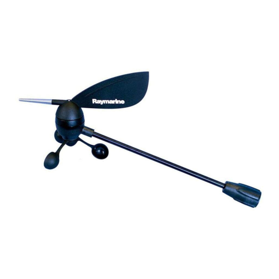
- Page 1 Wind Vane Service Manual Service Manual Document number: 83170-1 15 May 2004 Short arm E22078 Long arm E22079 D7006-1...
- Page 2 © Manual contents copyright Raymarine Ltd 2004. Raymarine® is a registered trademark of Raymarine Holdings.
-
Page 3: Table Of Contents
Safety ...................................3 Overview ..................................3 Tools & test equipment ..............................3 Construction ..................................4 Parts list ..................................5 Disassembly..................................5 Transducer arm ................................5 Wind vane base ................................6 Reassembly ...................................6 Wind vane base ................................6 Transducer arm ................................7 Testing ....................................7 PCB .......................................8 Circuit diagram ................................8 Layout diagram ................................9... -
Page 5: Introduction
Failure to do this could result in permanent damage to the equipment. Overview This manual provides servicing information for the Raymarine short-arm and long-arm wind vanes, part numbers E22078 and E22079, respectively. The following information is provided: • Tools and test equipment. -
Page 6: Construction
Wind Vane Service Manual Construction D6958-1 Figure 1: New Wind Vane exploded view... -
Page 7: Parts List
Disassembly To dismantle the wind vane: 1. Unscrew the locking ring (item 13) that secures the transducer arm (item 12) to the wind vane base (item 16), then sep- arate these two items. 2. Carry out the disassembly instructions for the transducer arm and wind vane base. -
Page 8: Wind Vane Base
To dismantle the wind vane base (item 16): 1. Using a suitable tool, remove and retain the nut (item 15) that secures the cable connector in the wind vane base. 2. Withdraw the transducer cable and connector through the bottom of the wind vane base. -
Page 9: Transducer Arm
7. Ensuring that the flats on the vane and the upper pod shaft are aligned, slide the vane to the upper pod shaft then secure with the screw removed during disassembly. Testing To check that a wind vane is serviceable: Figure 5 1. Connect the wind vane to a serviceable ST60 Wind instrument as in +12 V Screen Screen Yellow... -
Page 10: Pcb
Wind Vane Service Manual Vane direction Voltage between Blue & Black (sine signal) Voltage between Green & Black (cosine signal) Pointing forward Half the supply voltage measured at step 2. Half the supply voltage as measured at step 2 plus at least... -
Page 11: Layout Diagram
Wind Vane Service Manual Layout diagram D6957-1 (From Drawing No. 4531-001B) Component List Reference Part No. Description 3015-329-C WIND TX PCB 93CKEIXXX10U CAP CER 10uF 16V 93ADHBXX10N CAP. 10nF XR7 93ADHBXX10N CAP. 10nF XR7 93CKEIXXX10U CAP CER 10uF 16V 93ADHBXX10N CAP. - Page 12 Wind Vane Service Manual Reference Part No. Description 91AAAXXX33K RESISTOR 33K,0.063W,0603 91AAAXXX27K RESISTOR 27K 1% 0.063W 91AAAXXX33K RESISTOR 33K,0.063W,0603 91AAAXXX27K RESISTOR 27K 1% 0.063W 91AAAXXX4K7 RESISTOR 4.7K,1% 0.063W 0603 91AAAXXX4K7 RESISTOR 4.7K,1% 0.063W 0603 91AAAXXX33K RESISTOR 33K,0.063W,0603 91AAAXXX27K RESISTOR 27K 1% 0.063W 91AAAXXX33K RESISTOR 33K,0.063W,0603...
Need help?
Do you have a question about the Wind Vane and is the answer not in the manual?
Questions and answers