
Related Manuals for Raymarine Realvision RV-220P


Summary of Contents for Raymarine Realvision RV-220P
- Page 1 REALVISION ™ RV-2xx 3D Bronze Through-Hull Transducer Installation instructions English (en-US) Date: 06-2017 Document number: 88072-1 © 2017 Raymarine UK Limited...
-
Page 3: Obtain The Complete Documentation For Your Product
Raymarine will not warrant products subjected to high-pressure washing. Disclaimer Raymarine does not warrant that this product is error-free or that it is compatible with products manufactured by any person or entity other than Raymarine. -
Page 4: Declaration Of Conformity
Raymarine is not responsible for damages or injuries caused by your use or inability to use the product, by the interaction of the product with products manufactured by others, or by errors in information utilized by the product supplied by third parties. -
Page 5: Applicable Products
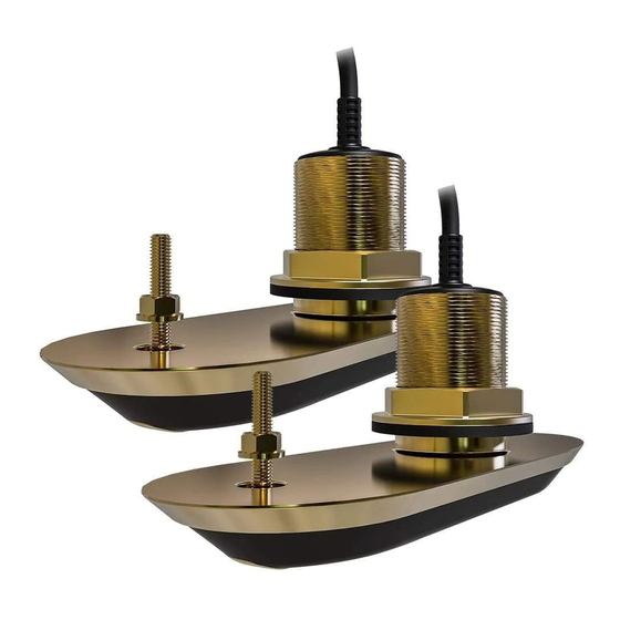
Applicable products This document is applicable to the RV-200, RV-212(P/S), and RV-220(P/S) RealVision™ 3D bronze thru-hull transducers. These transducers are capable of producing 3D sonar images when connected to RealVision™ 3D variant MFDs running LightHouse™ 3 software. Five transducers are available in the RV-2xx series, each having the same external shape and dimensions. -
Page 6: Tools Required
Tools required The following tools are required to install any of the transducers listed under “Applicable products”. Power drill 62 mm / 2⅜ inch hole cutter Drill bit (suitable size for drilling pilot holes) 9 mm / ⅜ inch drill bit (for drilling anti-rotation bolt hole) Half round file 75 mm / 3 inch wrench (spanner) or suitable size adjustable wrench (spanner) Marine grade sealant (non-acetate based) -
Page 7: Testing The Transducer
Channel). 6. Check that accurate depth and temperature readings are displayed. 7. If you experience difficulties obtaining readings then contact Raymarine Technical Support. Warning: Transducer operation Only test and operate the transducer in the water. Do NOT operate out of water as overheating may occur. - Page 8 Planing hull Outboard or I/O — mount forward and to the side of the propeller(s) Planing hull Inboard — mount forward of the propeller(s) and shaft(s) Planing hull Stepped hull — mount on the first step as far aft as possible Displacement Displacement hull —...
- Page 9 • Transducers should be installed in a location where no load will be applied to the transducers during, launching, lifting, trailering and storage of the boat. • Transducers must be installed in the correct orientation, with the anti-rotation bolt closest to the stern of the vessel.
- Page 10 – choose mounting positions that are at least 300 mm (12 inches) below the water line. • Transducers should be installed in a location where there is sufficient clearance inside the hull to fit the nut and have at least 100 mm (4 in) of headroom to allow for withdrawal. •...
- Page 11 Important: • Do NOT use the transducer cable to lift or suspend the transducer; always support the transducer body directly during installation. • The threads on the Hull nut may be sharp, ensure that the supplied Cable protector is fitted to the Hull nut before feeding the transducer cable through the nut.
- Page 12 Hull nut Rubber washer Anti-rotation bolt Transducer stem Anti-rotation bolt cap Transducer Marine grade sealant (non-acetate based) Direction of vessel’s bow 1. Using the location guidelines provided, ensure you have selected an appropriate location for the transducer. (See Location requirements.) 2.
- Page 13 23. Remove the Cable protector by pulling the 2 tabs away from the back of the Hull nut. 24. Apply a thick bead of marine grade sealant to the bottom face of the Hull nut. 25.Screw the hull nut onto the threaded stem-tube and tighten by hand. 26.Fully tighten the hull nut using a suitable sized wrench (spanner).
- Page 14 Important: Do NOT overtighten. Overtightening can cause damage to the hull which may result in water leaking into the vessel. 30. Apply a small amount of marine grade sealant to the inside of the anti-rotation bolt cap. 31. Fit the anti-rotation bolt cap by pressing it firmly into the hole in the bottom face of the transducer. Ensure that the anti-rotation bolt cap (1), is oriented correctly, with the embossed “BOW”...
-
Page 15: Cable Routing
Cable routing Cable routing requirements for the transducer cable. Important: To avoid interference, the cable must be routed as far away from VHF radio antenna cables as possible. • Check that the cable is long enough to reach the equipment it will be connected to. If you are installing split-pair transducers, you must use a Y-cable (A80478) along with an extension cable to connect the transducers to your multifunction display. -
Page 16: Attaching The Connector Locking Collar
Attaching the connector locking collar The supplied cable is provided with a separate locking collar assembly, ensuring that the cable connection is secure. This procedure describes how to attach the locking collar to the cable connector. The locking collar parts are supplied in a separate bag, in the package with your product. Important: Ensure that you route the cable all the way to its destination before attaching the locking collar. - Page 17 The split-ring slides easily for approximately 1 cm onto the connector, before butting up against the connector moulding. 3. Carefully insert the pointed end of the supplied tool into the split-ring’s gap (labelled ‘C’ in the illustration).
- Page 18 The tool widens the gap in the split ring, enabling the split ring to be pushed further back onto the connector in the following step. Important: Always use the supplied tool when attaching the split ring. The split ring may become overstretched and break if you try to attach it without using the tool.
- Page 20 6. Slide the locking collar towards the plug-end of the connector, rotating the collar as necessary to ensure that the lugs on the locking collar (labelled ‘D’ in the illustration) pass through the channels (labelled ‘E’) in the split-ring. The locking collar slides easily towards the plug-end of the connector, before butting up against the split-ring moulding.
-
Page 21: Making Connections
As you pull the locking collar, it clicks into place over the split-ring. The locking collar stays in position on the connector, but rotates freely. Making connections Follow the steps below to connect the transducer cable to your multifunction display. 1. - Page 22 Cable ferrite installation Your product is supplied with a cable ferrite. To ensure EMC Compliance, the supplied ferrite must be fitted to the power cable according to the following instructions. 1. Transducer connector. 2. The supplied cable ties should be used to secure the ferrite in position. 3.
- Page 24 Raymarine Marine House, Cartwright Drive, Fareham, Hampshire. PO15 5RJ. United Kingdom. Tel: +44 (0)1329 246 700 www.raymarine.com a brand by...
Need help?
Do you have a question about the Realvision RV-220P and is the answer not in the manual?
Questions and answers