
Related Manuals for Raymarine AUTOHELM ST50 PLUS DEPTH


Summary of Contents for Raymarine AUTOHELM ST50 PLUS DEPTH
- Page 1 Distributed by Any reference to Raytheon or RTN in this manual should be interpreted as Raymarine. The names Raytheon and RTN are owned by the Raytheon Company.
- Page 2 DEPTH Operation and Installation Nautech Limited, Anchorage Park, Portsmouth PO3 5TD. England Telephone (0705) 69361 I. Fax (0705) 694642...
- Page 3 Autohelms policy of continuous improvement and updating ma); change product specifications without prior notice Copyright Nautech 1993...
- Page 4 Package Contents The following items are included in the ST50 Plus Depth package: 1. ST50 Pius Depth control head 2. Fixing studs (2 offI 3. Thumb nuts (2 oftI 4. Fitting template 5. Power cable 6. Depth transducer (through hull) with 14m(45ftI of cable 7.
-
Page 5: Table Of Contents
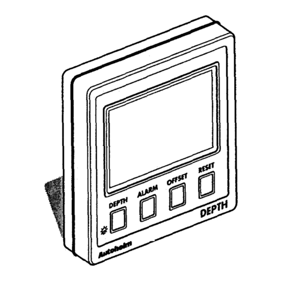
Contents Introduction ................. Chapter 1: Control Head Installation ......... 1.1 Sing ................1.2 Mounting Procedure ............1.3 Power Supply (stanchalone operation) ........t 1.4 Power Supply (SeaTalk operation) ..... ;‘....f 1.5 Connection of Separated Instruments ......... ; 1.6 Ring Connection ............. 1.7 Connection to SeaTalk Compatible Autopilots ...... - Page 6 The ST50 Plus Depth is a SeaTalk compatible, multifunction instrument that employs a powerful echo sounder to give excellent performance over a wide range of sea conditions. Deep, shallow, anchor watch alarms can be set to provide visual and audible warnings when the water depth reaches selected thresholds.
-
Page 7: Sing
Chapter 1: Confrol Head Installation Chapter i: Coniroi i-&j ins&&h 38 .75mm (1.5in) 1.1 Sing The ST50 Plus Depth is designed for above or below deck installafion where it is: Easily readable by the helmsman Protected against physical damage ... -
Page 8: Mounting Procedure
1: Control Head Installation Bracket Mounting The ST50 Plus Depth can, as an alternative, be bracket mounted using the Cable boss 2 Fiiing studs 3lhumb nuts 4Gashet 1.2 Mounting Procedure Flush Mounting clean, 1. Make sure that the selected location is smooth and flat. -
Page 9: Power Supply (Stanchalone Operation)
ST50 Plus Depth Operation and ImtaUation Handbook Chapter I: Control Head Installation 1.3 Power Supply (stand-alone operation) 1.5 Connection of Separated lnsttuments Separated instruments can be connected using one of the range of SeaTalk Extension Cables. These cables are supplied with a SeaTalk connecMitted to each end. -
Page 10: Ring Connection
Chapter 2: Transducer installation ST50 Plus Depth Operation and Installation Handbook Chapter 2: Transducer Installation 1.6 Ring Connection Installations with large numbers of instruments on a SeaTalk bus may require 2.1 Connection to the Control Head a second ringmain connection to the power supply breaker to prevent excessive voltage drops. - Page 11 Chapter 2: Transducer Installation depth readings the transducer should be sited within the For accurate shaded clear flow areas. Cabling 1. Run the cable back to the control head. Sail 2 Plmningfxnw 3 Displacementpower The transducer should also: Note: Avoid fluorescent lights, engines, radio transmitting equipment etc. as these be ahead of the propeilers (loo/o W.L.
-
Page 12: Chapter 3: Fault Finding And Maintenance
Chapter 3: Fault Finding and Maintenance Chapter 3: Fauit Finding and Maintenance 3.1 Fault Finding All Autohelm products are, prior to packing and shipping, subjected to comprehensive test and quality assurance programmes. However, if a fz arises with the ST50 Flus Depth, the following table will help to identify the probable cause and provide the most likely cure. - Page 13 Chapter 4: Operation As it leaves the factory the ST50 Plus Depth is set with: ‘depth units in feet Certain atmospheric conditions may cause condensation to form on the transducer off set set to 0 feet control head window. This will not harm the unit and can be cleared by ...
- Page 14 Handbook Chapter 4: Operation . .._. ..-. .-.-__ ..___._ Depth Key Notes Minimum Depth Minimum depth can be reset by pressing RESR: Minimum depth returns to current depth after 8 seconds. Display Contrast The display contrast is automatically adjusted when the tights are turnedon. Fathoms minimum depth.
-
Page 15: Chapter 4: Operation
Chapter 4: Operation Shallow Alarm The shallow alarm has priority over all alarms. The shallow alarm will sound until it is silenced, however, the shallow alarm legend continues to flash until the depth rises above the setthreshold. Deep/Alarm shallow to deep and deep to shallowwaters. Unless it is silenced, the deep alarm sounds for 30 seconds. -
Page 16: Reset Key
Chapter 4: Operaibn Offset Key Notes The off set value can be positive or negative: depih measured from the keel is negative and depth to the waterline positive. The offset display will return to water depth 8 seconds after the last key Reset Key Notes Reset Key Notes press... -
Page 17: Display Contrast
ST50 Plus Depth Operation and lnstaiiation Handbook Chapter 5: CODE Lock Security 4.5 Display Contrast The contrast can be adjusted to achieve optimum legibility at any angle. The ST50 Plus range incorporates an anti-theft feature called ‘CODE Lock’. Designed to protect individual instruments or complete systems ir - D e c r e a s e vulnerable areas, ‘CODE Lock is a four digit number that you programmc into the permanent memory of a selected ‘master’... -
Page 18: Chapter 5: Code Lock Security
ST50 Plus Depth Operation and Installation Handbook Chapter 5: CODE Lock Security Once Only Entry In the ‘Power& mode’, the ST50 Plus is configured so that you have to Action Display Shows enter the four digit number on the master instrument every time the system is switched on. -
Page 19: Chapter 6: Calibration
Chapter 6: Calibration Handbook Chapter 6: Calibration Display Shows Action As it leaves the factory the ST50 flus Depth is set to dispfay depth u&s in Press and DEPTH and ALARM together for CAL after 2 seconds and feet. These settings, together and other navigational features, can be VER X.X after 4 seconds 4 seconds changed (e.g., Feet to Metresjas described in this section. -
Page 20: Initial Calibration
Chapter 6: Calibration Initial Calibration Notes 6.1 Initial Calibration Alarms The shallow, deep, low anchor, high anchor and offset displays can be adjusted using the keys. RESET key is used to enable/disablethe alarms. ALARM Alternating between feet and metres is achieved by pressing RESIX Exii Initial Calibration To exit initial calibration and store the new settings, press DEPTH and together for 2 seconds. -
Page 21: Intermediate Calibration
Chapter 6: Calibration Intermediate Calibration Notes Repeater mode allows the ST50 Hus Depth to repeat speed related data already on the SeaTalk bus. There are two settings: Note: Exit Intermediate Calibration To exii intermediate calibration and store the new settings, press DEPTH and SECURITY... -
Page 22: Extended Calibration
Chapter 6: Calibration Extended Calibration Notes RESET keys. Calibration Calibration allows you to protect your selected settings. When calibration is enabled the initial and intermediate calibration settings cannot be modified. CAL 1 = Calibration unlocked, i.e. normal access Once locked, calibration can be unlocked by entering extended calibration and selecting 1, calibration unlocked. -
Page 23: Chapter 7: General Specification
Chapter 7: General Specification eration and lnstailation Handbook Chapter 7: General Specification Dimensions: Power supply: Power consumption: 50ma (normal) Temperature range: 0 to 70 deg.C Shallow alarm: feet 3 to 33 Deep alarm: feet (4 to 4 metres) Offset: -9.9 to 9.9 Anchor alarm: Minimum depth function: Reset on powerup...
Need help?
Do you have a question about the AUTOHELM ST50 PLUS DEPTH and is the answer not in the manual?
Questions and answers