Sign In
Upload
Manuals
Brands
Arcteq Manuals
Relays
AQ-F215
Arcteq AQ-F215 Manuals
Manuals and User Guides for Arcteq AQ-F215. We have
5
Arcteq AQ-F215 manuals available for free PDF download: Instruction Manual, User Manual
Arcteq AQ-F215 Instruction Manual (546 pages)
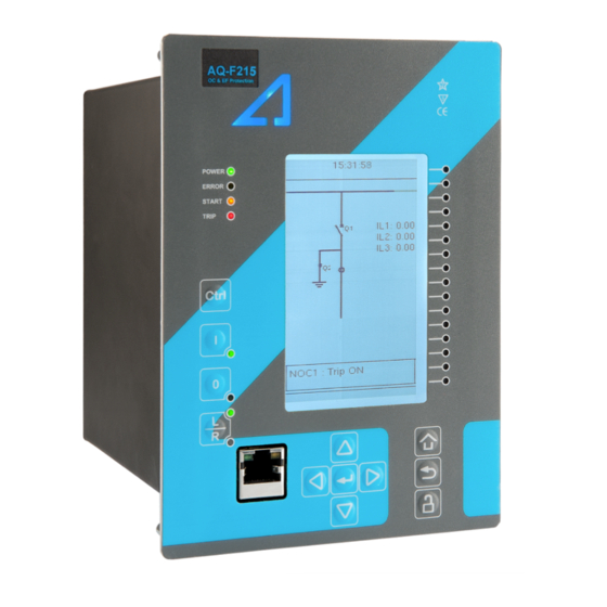
Feeder protection device
Brand:
Arcteq
| Category:
Protection Device
| Size: 29.63 MB
Table of Contents
Table of Contents
2
Document Inf
7
Document Informa Ormation Tion
7
Version 2 Revision Notes
7
Version 1 Revision Notes
10
Safety Information
12
Abbreviations
12
General
15
Device User Int Vice User Interface Erface
16
Panel Structure
16
Local Panel Structure
16
MIMIC and Main Menu
17
Basic Configuration
17
Navigation in the Main Configuration Menus
18
General Menu
18
Protection Menu
22
Control Menu
28
Communication Menu
43
Measurement Menu
46
Monitoring Menu
52
Configuring User Levels and Their Passwords
55
Functions Unctions
58
Functions Included in AQ-F215
58
Measurements
60
Current Measurement and Scaling
60
Voltage Measurement and Scaling
77
Voltage Memory
89
Power and Energy Calculation
92
Frequency Tracking and Scaling
100
General Menu
104
Protection Functions
106
General Properties of a Protection Function
106
Non-Directional Overcurrent Protection (I>; 50/51)
115
Non-Directional Earth Fault Protection (I0>; 50N/51N)
123
Directional Overcurrent Protection (Idir>; 67)
128
Directional Earth Fault Protection (I0Dir>; 67N/32N)
137
Intermittent Earth Fault Protection (I0Int>; 67NT)
151
Negative Sequence Overcurrent/ Phase Current Reversal/ Current Unbalance Protection (I2>; 46/46R/46L)
161
Harmonic Overcurrent Protection (Ih>; 50H/51H/68H)
167
Circuit Breaker Failure Protection (CBFP; 50BF/52BF)
174
Low-Impedance or High-Impedance Restricted Earth Fault/ Cable End Differential Protection (I0D>; 87N)
189
Overvoltage Protection (U>; 59)
199
Undervoltage Protection (U<; 27)
207
Neutral Overvoltage Protection (U0>; 59N)
216
Sequence Voltage Protection (U1/U2>/<; 47/27P/59PN)
223
Overfrequency and Underfrequency Protection (F>/<; 81O/81U)
231
Rate-Of-Change of Frequency (Df/Dt>/<; 81R)
238
Overpower Protection (P>; 32O)
244
Underpower Protection (P<; 32U)
248
Reverse Power Protection (Pr; 32R)
252
Voltage-Restrained Overcurrent Protection (IV>; 51V)
256
Line Thermal Overload Protection (TF>; 49F)
261
Resistance Temperature Detectors (RTD)
282
Programmable Stage (Pgx>/<; 99)
288
Arc Fault Protection (Iarc>/I0Arc>; 50Arc/50Narc)
298
Control Functions
308
Common Signals
308
Setting Group Selection
309
Object Control and Monitoring
318
Indicator Object Monitoring
327
Auto-Recloser (79)
328
Zero Sequence Recloser (U0> RECL; 79N)
357
Cold Load Pick-Up (CLPU)
360
Switch-On-To-Fault (SOTF)
370
Synchrocheck (ΔV/Δa/Δf; 25)
373
Milliampere Output Control
386
Vector Jump (Δφ; 78)
389
Programmable Control Switch
394
Analog Input Scaling Curves
395
Logical Outputs
397
Logical Inputs
398
Monitoring Functions
400
Current Transformer Supervision
400
Voltage Transformer Supervision (60)
411
Circuit Breaker Wear Monitoring
416
Current Total Harmonic Distortion (THD)
421
Fault Locator (21FL)
426
Disturbance Recorder (DR)
428
Event Logger
438
Measurement Recorder
439
Measurement Value Recorder
444
Communica a Tion
450
Communic Tion
450
Connections Menu
450
Time Synchronization
452
Internal
452
Ntp
453
Communication Protocols
454
Iec 61850
454
Goose
455
Modbus/Tcp and Modbus/Rtu
457
Iec 103
458
Iec 101/104
458
Spa
461
Dnp3
461
Modbus I/O
464
Analog Fault Registers
464
Real-Time Measurements to Communication
465
Connections of AQ-F215
468
Application Example and Its Connections
470
Two-Phase, Three-Wire ARON Input Connection
471
Trip Circuit Supervision (95)
472
Construction and Installation Tion
476
Construction
476
CPU Module
478
Current Measurement Module
481
Voltage Measurement Module
482
Option Cards
483
Digital Input Module (Optional)
483
Digital Output Module (Optional)
486
Point Sensor Arc Protection Module (Optional)
487
RTD Input Module (Optional)
489
Serial RS-232 Communication Module (Optional)
490
LC or RJ45 100 Mbps Ethernet Communication Module (Optional)
492
Double ST 100 Mbps Ethernet Communication Module (Optional)
493
Double RJ45 10/100 Mbps Ethernet Communication Module (Optional)
495
Milliampere (Ma) I/O Module (Optional)
496
Dimensions and Installation
497
Technic Echnical da al Data Ta
500
Hardware
500
Measurements
500
Current Measurement
500
Voltage Measurement
502
Voltage Memory
502
Power and Energy Measurement
503
Frequency Measurement
504
CPU & Power Supply
504
Auxiliary Voltage
504
CPU Communication Ports
505
CPU Digital Inputs
506
CPU Digital Outputs
506
Option Cards
508
Digital Input Module
508
Digital Output Module
508
Point Sensor Arc Protection Module
509
Milliampere Module (Ma out & Ma In)
510
RTD Input Module
511
Serial Fiber Communication Module
511
Double LC 100 Mbps Ethernet Communication Module
512
Double ST 100 Mbps Ethernet Communication Module
512
Display
513
Functions
513
Protection Functions
513
Non-Directional Overcurrent Protection (I>; 50/51)
513
Non-Directional Earth Fault Protection (I0>; 50N/51N)
514
Directional Overcurrent Protection (Idir>; 67)
515
Directional Earth Fault Protection (I0Dir>; 67N/32N)
517
Intermittent Earth Fault Protection (I0Int>; 67NT)
518
Negative Sequence Overcurrent/ Phase Current Reversal/ Current Unbalance Protection (I2>; 46/46R/46L)
519
Harmonic Overcurrent Protection (Ih>; 50H/51H/68H)
520
Circuit Breaker Failure Protection (CBFP; 50BF/52BF)
521
Low-Impedance or High-Impedance Restricted Earth Fault/ Cable End Differential Protection (I0D>; 87N)
521
Overvoltage Protection (U>; 59)
522
Undervoltage Protection (U<; 27)
523
Neutral Overvoltage Protection (U0>; 59N)
524
Sequence Voltage Protection (U1/U2>/<; 47/27P/59NP)
525
Overfrequency and Underfrequency Protection (F>/<; 81O/81U)
526
Rate-Of-Change of Frequency Protection (Df/Dt>/<; 81R)
527
Line Thermal Overload Protection (TF>; 49F)
528
Overpower (P>; 32O), Underpower (P<; 32U) and Reverse Power (Pr; 32R) Protection
528
Voltage-Restrained Overcurrent Protection (IV>; 51V)
529
Resistance Temperature Detectors (RTD)
530
Arc Fault Protection (Iarc>/I0Arc>; 50Arc/50Narc) (Optional)
531
Control Functions
532
Setting Group Selection
532
Object Control and Monitoring
532
Indicator Object Monitoring
533
Auto-Reclosing (0 → 1; 79)
533
Cold Load Pick-Up (CLPU)
534
Switch-On-To-Fault (SOTF)
534
Zero Sequence Recloser (79N)
535
Vector Jump (Δφ; 78)
535
Synchrocheck (ΔV/Δa/Δf; 25)
536
Monitoring Functions
537
Current Transformer Supervision
537
Voltage Transformer Supervision (60)
537
Circuit Breaker Wear Monitoring
538
Current Total Harmonic Distortion
539
Fault Locator (21FL)
539
Disturbance Recorder
540
Event Logger
540
Tests and Environmental
541
Ordering Inf Dering Informa Ormation Tion
544
Contact and R Ence Informa Ormation Tion
546
Advertisement
Arcteq AQ-F215 Instruction Manual (489 pages)
Feeder protection IED
Brand:
Arcteq
| Category:
Protection Device
| Size: 28.64 MB
Table of Contents
Table of Contents
2
Document Inf
8
Document Informa Ormation Tion
8
Version 2 Revision Notes
8
Version 1 Revision Notes
10
Abbr Bbre E Via Viations Tions
12
General
14
IED User Interface Erface
15
Panel Structure
15
Local Panel Structure
15
MIMIC and Main Menu
16
Basic Configuration
16
Navigation in the Main Configuration Menus
16
General Menu
17
Protection Menu
20
Control Menu
26
Communication Menu
41
Measurement Menu
44
Monitoring Menu
50
Configuring User Levels and Their Passwords
53
Functions Unctions
56
Functions Included in AQ-F215
56
Measurements
58
Current Measurement and Scaling
58
Voltage Measurement and Scaling
72
Power and Energy Calculation
83
Frequency Tracking and Scaling
90
Protection Functions
93
General Properties of a Protection Function
93
Non-Directional Overcurrent Protection (I>; 50/51)
102
Non-Directional Earth Fault Protection (I0>; 50N/51N)
109
Directional Overcurrent Protection (Idir>; 67)
113
Directional Earth Fault Protection (I0Dir>; 67N/32N)
121
Intermittent Earth Fault Protection (I0Int>; 67NT)
134
Negative Sequence Overcurrent/ Phase Current Reversal/ Current Unbalance Protection (I2>; 46/46R/46L)
143
Harmonic Overcurrent Protection (Ih>; 50H/51H/68H)
148
Circuit Breaker Failure Protection (CBFP; 50BF/52BF)
155
Low-Impedance or High-Impedance Restricted Earth Fault/ Cable End Differential Protection (I0D>; 87N)
170
Overvoltage Protection (U>; 59)
179
Undervoltage Protection (U<; 27)
186
Neutral Overvoltage Protection (U0>; 59N)
194
Sequence Voltage Protection (U1/U2>/<; 47/27P/59PN)
200
Overfrequency and Underfrequency Protection (F>/<; 81O/81U)
208
Rate-Of-Change of Frequency (Df/Dt>/<; 81R)
213
Overpower Protection (P>; 32O)
219
Underpower Protection (P<; 32U)
222
Reverse Power Protection (Pr; 32R)
226
Voltage-Restrained Overcurrent Protection (IV>; 51V)
229
Line Thermal Overload Protection (TF>; 49F)
233
Resistance Temperature Detectors
253
Arc Fault Protection (Iarc>/I0Arc>; 50Arc/50Narc)
258
Programmable Stage (Pgx>/<; 99)
267
Voltage Memory
281
Control Functions
284
Setting Group Selection
284
Object Control and Monitoring
293
Indicator Object Monitoring
303
Auto-Recloser (79)
304
Cold Load Pick-Up (CLPU)
330
Switch-On-To-Fault (SOTF)
339
Synchrocheck (ΔV/Δa/Δf; 25)
341
Milliampere Output Control
353
Vector Jump (Δφ; 78)
355
Programmable Control Switch
360
Analog Input Scaling Curves
361
Logical Outputs
363
Logical Inputs
364
Monitoring Functions
365
Current Transformer Supervision
365
Voltage Transformer Supervision (60)
375
Circuit Breaker Wear
379
Fault Locator (21FL)
383
Total Harmonic Distortion (THD)
385
Disturbance Recorder (DR)
390
Measurement Recorder
401
Measurement Value Recorder
405
Sy y St Stem Int 6 S Em Integra Egration Tion
410
Communication Protocols
410
Ntp
410
Modbus/Tcp and Modbus/Rtu
411
Modbus I/O
412
Iec 61850
412
Goose
414
Iec 103
414
Dnp3
415
Iec 101/104
417
Spa
419
Analog Fault Registers
419
Real-Time Measurements to Communication
419
Connections and Applica a Tion Examples
422
Connections of AQ-F215
422
Application Example and Its Connections
424
Two-Phase, Three-Wire ARON Input Connection
425
Trip Circuit Supervision (95)
426
Construction and Installa
431
Construction and Installation Tion
431
Construction
431
CPU Module
434
Current Measurement Module
436
Voltage Measurement Module
437
Digital Input Module (Optional)
438
Digital Output Module (Optional)
440
Arc Protection Module (Optional)
441
RTD Input Module (Optional)
442
Serial RS-232 Communication Module (Optional)
443
LC 100 Mbps Ethernet Communication Module (Optional)
445
Double ST 100 Mbps Ethernet Communication Module (Optional)
446
Double RJ-45 10/100 Mbps Ethernet Communication Module (Optional)
448
Milliampere (Ma) I/O Module (Optional)
450
Dimensions and Installation
450
Technic Echnical da al Data Ta
453
Hardware
453
Measurements
453
Current Measurement
453
Voltage Measurement
454
Power and Energy Measurement
455
Frequency Measurement
455
CPU & Power Supply
455
Auxiliary Voltage
455
CPU Communication Ports
456
CPU Digital Inputs
457
CPU Digital Outputs
458
Option Cards
458
Digital Input Module
458
Digital Output Module
459
Arc Protection Module
459
Milliampere Module (Ma out & Ma In)
460
RTD Input Module
461
Serial Fiber Communication Module
461
Double LC 100 Mbps Ethernet Communication Module
461
Display
462
Functions
462
Protection Functions
462
Non-Directional Overcurrent Protection (I>; 50/51)
462
Non-Directional Earth Fault Protection (I0>; 50N/51N)
463
Directional Overcurrent Protection (Idir>; 67)
464
Directional Earth Fault Protection (I0Dir>; 67N/32N)
465
Intermittent Earth Fault Protection (I0Int>; 67NT)
466
Negative Sequence Overcurrent/ Phase Current Reversal/ Current Unbalance Protection (I2>; 46/46R/46L)
466
Harmonic Overcurrent Protection (Ih>; 50H/51H/68H)
467
Circuit Breaker Failure Protection (CBFP; 50BF/52BF)
468
Low-Impedance or High-Impedance Restricted Earth Fault/ Cable End Differential Protection (I0D>; 87N)
469
Overvoltage Protection (U>; 59)
469
Undervoltage Protection (U<; 27)
470
Neutral Overvoltage Protection (U0>; 59N)
471
Sequence Voltage Protection (U1/U2>/<; 47/27P/59NP)
472
Overfrequency and Underfrequency Protection (F>/<; 81O/81U)
472
Rate-Of-Change of Frequency Protection (Df/Dt>/<; 81R)
473
Line Thermal Overload Protection (TF>; 49F)
474
Overpower (P>; 32O), Underpower (P<; 32U) and Reverse Power (Pr; 32R) Protection
474
Voltage-Restrained Overcurrent Protection (IV>; 51V)
475
Resistance Temperature Detectors
476
Arc Fault Protection (Iarc>/I0Arc>; 50Arc/50Narc) (Optional)
476
Voltage Memory
477
Control Functions
478
Setting Group Selection
478
Object Control and Monitoring
478
Auto-Reclosing (0 → 1; 79)
478
Cold Load Pick-Up (CLPU)
479
Switch-On-To-Fault (SOTF)
480
Vector Jump (Δφ; 78)
480
Zero Sequence Recloser (79N)
480
Synchrocheck (ΔV/Δa/Δf; 25)
481
Monitoring Functions
482
Current Transformer Supervision
482
Voltage Transformer Supervision (60)
482
Circuit Breaker Wear Monitoring
483
Total Harmonic Distortion
483
Fault Locator (21FL)
484
Disturbance Recorder
484
Tests and Environmental
485
Arcteq AQ-F215 Instruction Manual (380 pages)
Feeder protection IED
Brand:
Arcteq
| Category:
Power distribution unit
| Size: 18.83 MB
Table of Contents
Table of Contents
2
1 Manual Revision Notes
7
Version 2 Revision Notes
7
Version 1 Revision Notes
7
2 Abbreviations
9
3 General
10
4 IED User Interface
11
Panel Structure
11
AQ 200 Series Local Panel Structure
11
MIMIC and Main Menu
12
Basic con Guration
12
Navigation in Main con Guration Menus
12
General Menu
13
Protection Menu
13
Device Info
13
Stage Activation
14
Info-Menu
21
Settings-Menu
22
Registers-Menu
23
IO-Menu
24
Events-Mask
25
Control Menu
25
Controls Enabled
26
Setting Groups
26
Objects
27
Control Functions
30
Device IO
31
Communication Menu
35
Connections-Menu
36
Protocols-Menu
36
Measurement Menu
37
Transformers
37
Current and Voltage Measurement
38
Monitoring Menu
40
Monitors Enabled
40
Monitor Functions
41
Device Diagnostics
43
User Level Password con Guration
44
Functions Included in AQ-F213
45
Current Measurement and Scaling
46
CT Scaling Example
48
ZCT Scaling Example
51
Troubleshooting
52
Settings
55
Voltage Measurements and Scaling
58
VT Scaling Example
59
Power and Energy Calculation
66
Energy Measurements
71
Frequency Tracking and Scaling
74
General Menu
76
Protection Functions
77
General Properties of a Protection Function
77
Pick-Up Characteristics
79
Function Blocking
80
Operating Time Characteristics for Trip and Reset
80
Stage Forcing
91
Non-Directional Overcurrent I> (50/51)
91
Measured Input Values
92
General Settings
92
Non-Directional Earth Fault I0> (50N/51N)
96
Directional Overcurrent Idir> (67)
100
Directional Earth Fault I0Dir> (67N)
106
Real-Time Info Displayed by the Function
112
Current Unbalance I2
115
Harmonic Overcurrent Ih> (50H/51H/68H)
120
Circuit Breaker Failure Protection CBFP (50BF)
124
Restricted Earth Fault / Cable End Differential (REF) I0D> (87N)
138
Overvoltage U
144
Undervoltage U
149
Neutral Voltage U0> (59N)
154
Sequence Voltage U1/U2>/<(59P/27P/47)
160
Over- and Underfrequency F>/< (81O/81U)
166
Rate-Of-Change of Frequency Protection Df/Dt (81R)
170
Over Power P> (32O)
174
Under Power P< (32U)
176
Reverse Power Pr (32R)
179
Vector Jump Protection (78)
181
Line Thermal Overload Protection TF> (49F)
185
Voltage Memory Function
202
Arc Fault Protection Iarc>/I0Arc>(50Arc/50Narc)
205
Programmable Stage
212
Control Functions
225
Setting Group Selection (SGS)
225
Object Control and Monitoring (OBJ)
231
Blocking and Interlocking
235
Indicator Object Monitoring (CIN)
236
Input Signals for Indication Status Monitoring
236
Auto-Reclosing 0 → 1 (79)
238
Auto-Reclosing Scheme in Radial Network
239
Auto-Reclosing Sequence from Trip with Two Shot Failure
240
Auto-Reclosing Sequence from Trip with Two Shot, High Speed Succeeds
244
Auto-Reclosing Sequence from Start with Two Shot Failure
245
Auto-Recloser IO
251
Input Signals for Autorecloser Control
252
Output Signals of Auto-Recloser
253
Setting Parameters
254
Inhibit and Locked States of Auto-Recloser Function
257
Displaying Auto Recloser Timers in MIMIC View
257
Events and Registers
257
Cold Load Pick-Up (CLPU)
261
Auto-Recloser Operation Counters
261
Switch on to Fault (SOTF)
270
Input Signals
271
Ma Output Control
272
Milliamp Outputs
272
Milliamp Input
274
Programmable Control Switch
276
Monitoring Functions
276
Current Transformer Supervision (CTS)
276
Fuse Failure VTS (60)
285
Operating Time Characteristics for Activation
287
Disturbance Recorder (DR)
288
Analog and Digital Recording Channels
288
Recording Settings and Triggering
289
Events
290
Application Example
290
How to Estimate the Max Length of Total Recording Time
291
Aqviewer
292
Measurement Recorder
295
Circuit Breaker Wear-Monitor (CBW)
299
Circuit Breaker Characteristics Settings
301
Pick-Up Characteristics for Alarming
301
Fault Locator (21FL) X → Km
303
Fault Locator Triggering
304
Total Harmonic Distortion Monitor (THD)
305
Measurement Value Recorder
309
Reported Values
311
6 System Integration
313
Communication Protocols
313
Ntp
313
Modbustcp and Modbusrtu
313
Modbusio
314
Iec 61850
314
Goose
317
Dnp3
319
Iec 103
319
Iec 101/104
319
SPA Protocol
320
General IO Analog Fault Registers
320
Real Time Measurements to Communication
320
7 Applications and Connection Examples
323
Connections AQ-F213
323
Example Feeder Application Connection
325
3-Phase, 3-Wire ARON Input Connection
326
Trip Circuit Supervision (95)
327
8 Construction and Installation
331
CPU, IO and Power Supply Module
333
Current Measurement Module
335
Voltage Measurement Module
336
Binary Input Module (DI8) (Option)
337
Setting up the Activation and Release Delays
338
Binary Output Module (DO5) (Option)
339
Arc Protection Module (Option)
340
RTD & Ma Input Module (Option)
341
Serial RS232 Communication Module (Option)
342
LC100 Ethernet Communication Module (Option)
344
Maout & Mainput Module (Option)
345
Installation Dimensioning
345
9 Technical Data
348
Current Measurement
348
Hardware
348
Voltage Measurement
349
Power and Energy Measurement
349
Frequency Measurement
350
CPU & Power Supply
350
Auxiliary Voltage
350
CPU Communication Ports
350
CPU Binary Inputs
351
CPU Binary Outputs
352
Option Cards
353
Binary Input Module
353
Binary Output Module
353
Arc Protection Module
353
Maout & Main Module
354
RTD & Ma Input Module
355
RS232 & Serial Ber Communication Module
355
Double Lc100Mb Ethernet Module (Redundant)
355
Display
356
Functions
356
Protection Functions
356
Non-Directional Overcurrent (50/51) I
356
Non-Directional Earth Fault (50N/51N) I0
357
Directional Overcurrent (67) Idir
358
Directional Earth Fault (67N) Iodir
358
Current Unbalance (46/46R/46L) I2
360
Harmonic Overcurrent (50H/51H, 68) Ih
360
Circuit Breaker Failure Protection (50BF/52BF) CBFP
361
Restricted Earth Fault / Cable End Differential (87N) Iod
362
Overvoltage (59) U
362
Undervoltage (27) U
363
Neutral Overvoltage (59N) U0
364
Sequence Voltage (47/27PN/59PN) U1/2
364
Over-/Under Frequency (81O/81U) F
365
Rate-Of-Change-Of-Frequency (81R) Df/Dt
366
Line Thermal Overload (49L) TF
367
Over/Under/Reverse Power Protection (32/37) P>, P<, PREV
367
Resistance Temperature Detector Alarm (49RTD) T
368
Vector Jump (78) ΔΑ
368
Arc Protection (50ARC/50NARC) IARC> I0ARC> (Option)
369
Control Functions
369
Setting Group Selection
369
Object Control (OBJ)
370
Autoreclosing Function (79) 0
370
Cold Load Pick-Up (CLP)
371
Switch on to Fault (SOTF)
371
Synchrocheck (25)
371
Monitoring Functions
372
Current Transformer Supervision (CTS)
372
Fuse Failure VTS (60)
373
Disturbance Recorder (DR)
373
Circuit Breaker Wear Monitor (CBW)
374
Total Harmonic Distortion (THD)
374
Fault Locator (21FL) X → Km
374
Voltage Memory (Integrated in 67,21G)
375
Tests and Environmental
375
10 Ordering Information
378
11 Contact and Reference Information
379
Advertisement
Arcteq AQ-F215 Instruction Manual (424 pages)
Feeder Protection IED
Brand:
Arcteq
| Category:
Protection Device
| Size: 17.09 MB
Table of Contents
Table of Contents
5
Abbreviations
9
General
10
Ied User Interface
11
AQ 200 Series Local Panel Structure
11
IED Programming
11
Basic Configuration
11
Navigation in Main Configuration Menus
13
Functions of Aq-F215 Feeder Protection Ied
41
Measurements
42
Current Measurement and Scaling
42
Voltage Measurement and Scaling
54
Frequency Tracking and Sampling
65
Power and Energy Calculation
68
Protection Functions
76
General Properties of a Protection Function
76
Non-Directional over Current I> (50/51)
91
Non-Directional Earth Fault I0> (50N/51N)
98
Directional over Current Idir> (67)
104
Directional Earth Fault I0Dir> (67N)
113
Intermittent Earth Fault I0Int> (67NT)
123
Current Unbalance I2> (46)
132
Harmonic over Current IH> (50H/51H/68H)
138
Circuit Breaker Failure Protection (CBFP) (50BF)
147
Restricted Earth Fault / Cable End Differential (REF) I0D> (87N)
160
Thermal Overload Protection for Feeders T > (49F)
168
Over Voltage U> (59)
186
Under Voltage U< (27)
193
Sequence Voltage U1/U2>/< (59P/27P/47)
199
Neutral Voltage U0> (59N)
207
Over- and under Frequency F>/< (81O/81U)
215
Rate-Of-Change of Frequency Protection Df/Dt (81R)
220
Over Power P> (32O)
226
Under Power P< (32U)
230
Reverse Power Pr (32R)
236
Arc Fault Protection Iarc>/I0Arc>(50Arc/50Narc)
240
Control Functions
248
Setting Group Selection (SGS)
248
Object Control and Monitoring (OBJ)
256
Auto-Reclosing 0 1 (79)
266
Cold Load Pick-Up (CLPU)
295
Switch on to Fault (SOTF)
303
Synchrocheck Function ΔV/Δa/Δf (25)
305
Monitoring Functions
315
Current Transformer Supervision (CTS)
315
Voltage Transformer Supervision (60)
325
Disturbance Recorder (DR)
328
Measurement Recorder
339
Circuit Breaker Wear -Monitor (CBW)
340
Total Harmonic Distortion Monitor (THD)
346
System Integration
352
Communication Protocols
352
5.1.1 Ntp
352
Modbustcp and Modbusrtu
353
Modbusio
354
5.1.4 Iec 61850
354
5.1.5 Goose
358
Iec 103
359
5.1.7 Dnp3
360
Iec 101 / 104
360
SPA Protocol
361
Connections
362
Construction and Installation
366
CPU, IO and Power Supply Module
368
Current Measurement Module
369
Voltage Measurement Module
370
Digital Input Module DI8
371
Digital Output Module DO5
372
Arc Protection Module (Option)
374
RTD & Ma Input Module (Option)
375
Serial RS232 & Serial Fiber Module (Option)
377
Double LC 100 Mb Ethernet Module (Option)
378
Installation and Dimensions
378
Applications
381
3LN+U0 Connection Example
381
3-Phase, 3-Wire ARON Input Connection Example
382
Trip Circuit Supervision
383
Trip Circuit Open Coil Supervision with One Digital Input and Connected Trip Output
383
Trip Circuit Open Coil Supervision with One Digital Input and Connected and Latched Trip Output
385
Technical Data
387
Connections
387
Measurements
387
Auxiliary Voltage
390
Binary Inputs
390
Binary Outputs
391
Arc Protection Card (Option)
392
Communication Ports
393
Protection Functions
394
Current Protection Functions
394
Voltage Protection Functions
404
Power Protection Functions
407
Frequency Protection Functions
408
9.2.5 Arc Protection Function
410
9.3 Control Functions
411
Monitoring Functions
416
Tests and Environmental
420
Electrical Environment Compatibility
420
Physical Environment Compatibility
421
Casing and Package
421
Ordering Information
422
Reference Information
424
Arcteq AQ-F215 User Manual (26 pages)
Simulator
Brand:
Arcteq
| Category:
Switch
| Size: 3.01 MB
Table of Contents
Table of Contents
3
1 Aq-F215 Simulator
4
2 Simulator Parts
5
3 Simulator Operation
7
Things to Show in Normal Situation
8
Fault 1: Overcurrent Fault
11
Special Cases: Trip Circuit Fault (TCS)
13
Special Cases MCB (Miniature Circuit Breaker) Trip
15
Special Cases Breaker SF6 Pressure Low
17
Fault 2: Arc Fault in the Feeder (Zone2)
19
Fault 3: Arc Fault in the Bus
20
Fault 4: Unbalance Fault
21
Fault 5: Earth Fault
22
Fault 6: over Voltage
23
Fault 7: under Voltage
24
4 Reference Information
26
Advertisement
Related Products
Arcteq AQ F205
Arcteq AQ-F210
Arcteq AQ-F201
Arcteq AQ-F255
Arcteq AQ 1000
Arcteq AQ-T257
Arcteq AQ-S215
Arcteq AQ-F213
Arcteq AQ F3 0 Series
Arcteq AQ T3 Series
Arcteq Categories
Protection Device
Relays
Accessories
Industrial Electrical
Power distribution unit
More Arcteq Manuals
Login
Sign In
OR
Sign in with Facebook
Sign in with Google
Upload manual
Upload from disk
Upload from URL