Arcteq AQ-F215 User Manual
Simulator
Hide thumbs
Also See for AQ-F215:
- Instruction manual (546 pages) ,
- Instruction manual (424 pages) ,
- Instruction manual (380 pages)
Table of Contents
Advertisement
Quick Links
Advertisement
Table of Contents

Subscribe to Our Youtube Channel
Related Manuals for Arcteq AQ-F215


Summary of Contents for Arcteq AQ-F215
- Page 1 User Manual AQ-F215 Simulator...
- Page 2 Instruction manual – AQ-F215 Simulator 2 (26 Revision 1.00 Date 16.5.2014 Changes Revision 1.01 Date 13.3.2018 • Changes Updated visual look • Readability improvements Revision 1.02 Date 24.9.2020 • Changes Updated reference information...
-
Page 3: Table Of Contents
Instruction manual – AQ-F215 Simulator 3 (26 TABLE OF CONTENTS AQ-F215 SIMULATOR ....................4 SIMULATOR PARTS ....................5 SIMULATOR OPERATION ................... 7 3.1 Things to show in normal situation ................8 3.2 Fault 1: Overcurrent fault ..................... 11 3.2.1 Special cases: Trip circuit fault (TCS) ............... 13 3.2.2... -
Page 4: Aq-F215 Simulator
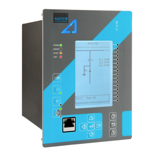
Instruction manual – AQ-F215 Simulator 4 (26 1 AQ-F215 S IMULATOR AQ-SIM F215 simulates basic outgoing feeder protection and control application. In the picture above is presented the front side of the simulator. Simulator consists of protection relay, feeder protection model and simulator unit. -
Page 5: Simulator Parts
Instruction manual – AQ-F215 Simulator 5 (26 IMULATOR PARTS Frontside Backside Digital network simulator controls... - Page 6 Instruction manual – AQ-F215 Simulator 6 (26...
-
Page 7: Simulator Operation
Instruction manual – AQ-F215 Simulator 7 (26 IMULATOR OPERATION Simulator is easy to use. Plug 110 – 230 VAC 50/60Hz power cord, switch power on and wait to relay to start. Now the simulator is ready to be used. (If simulator does not start... -
Page 8: Things To Show In Normal Situation
Instruction manual – AQ-F215 Simulator 8 (26 This is now the starting situation of the simulator and it is ready for starting demonstration. HINGS TO SHOW IN NORMAL SITUATION Normal operation... - Page 9 Instruction manual – AQ-F215 Simulator 9 (26 Line is grounded (follow mimic and see that currents are not flowing, voltages are still ok) From the configuration tool you can show the measurements and vectors of currents and voltages.
- Page 10 Instruction manual – AQ-F215 Simulator 10 (26...
-
Page 11: Fault 1: Overcurrent Fault
Instruction manual – AQ-F215 Simulator 11 (26 1: O AULT VERCURRENT FAULT In the simulator with arrow key down select the cursor to “Overcurrent” and press simulator enter button. Relay trips the outgoing feeder breaker and indicates trip of directional overcurrent. - Page 12 Instruction manual – AQ-F215 Simulator 12 (26 Relay event list can be demonstrated. This fault is tripped by directional overcurrent function by using voltage memory. This can be seen in the event list. Directional stage settings can be shown: Disturbance recording can be shown:...
-
Page 13: Special Cases: Trip Circuit Fault (Tcs)
Instruction manual – AQ-F215 Simulator 13 (26 From the recording can be seen the application. NOC2 is instant non-directional back up protection which is blocked by directional overcurrent DOC1 when the voltages are measurable. Operating time was set to 50 ms and the trip was given in 49.7 ms from the start of the fault. - Page 14 Instruction manual – AQ-F215 Simulator 14 (26 Apply the fault similarly than in normal case (press the Fault button to apply and again to clear the fault) Demonstrate that the incomer breaker has operated and the relay shows CBFP trip indication and the tripping function is DOC1 directional overcurrent function.
-
Page 15: Special Cases Mcb (Miniature Circuit Breaker) Trip
Instruction manual – AQ-F215 Simulator 15 (26 Clear the trip circuit fault by switching the TCS back to Ok position 3.2.2 S MCB ( PECIAL CASES MINIATURE CIRCUIT BREAKER TRIP To simulate voltage transformer fuse failure switch MCB to “trip” position. This causes that the voltages cannot be measured. - Page 16 Instruction manual – AQ-F215 Simulator 16 (26 Apply the fault similarly than in normal case (press the Fault button to apply and again to clear the fault) Demonstrate that the NOC2 function did trip this time (since the DOC1 function cannot operate when the VTS alarm is blocking its operation).
-
Page 17: Special Cases Breaker Sf6 Pressure Low
Instruction manual – AQ-F215 Simulator 17 (26 Clear the fuse fault by switching MCB trip to “Ok” position. 3.2.3 S PECIAL CASES REAKER PRESSURE LOW When breaker SF6 pressure is low it is not allowed to operate breaker at all, it cannot be allowed to close or open even there is fault. - Page 18 Instruction manual – AQ-F215 Simulator 18 (26 Also, in the configuration tool under objects can be seen that the breaker object controls open and close are both blocked. Apply the fault similarly than in normal case (press the Fault button to apply and again to...
-
Page 19: Fault 2: Arc Fault In The Feeder (Zone2)
Instruction manual – AQ-F215 Simulator 19 (26 Clear the low SF6 pressure alarm by setting the “BK SF6” switch to “Ok” position. 3.3 F 2: A AULT RC FAULT IN THE FEEDER Arc fault in the feeder includes overcurrent and light input from sensor Z2 Activate “Arc feeder”... -
Page 20: Fault 3: Arc Fault In The Bus
Instruction manual – AQ-F215 Simulator 20 (26 Demonstrate in the disturbance recording that the operating of the Arc protection is very fast compared to overcurrent trip. (In the simulator the light information comes through aux relay so it is delayed by additional 5ms. This time can be deducted from the operating time result). -
Page 21: Fault 4: Unbalance Fault
Instruction manual – AQ-F215 Simulator 21 (26 Demonstrate that in the bus fault incomer breaker as well as outgoing feeder breaker are tripped. If the load of the feeder is supplying motor loads or similar which can back feed short circuit current it should be separated from fault as well. -
Page 22: Fault 5: Earth Fault
Instruction manual – AQ-F215 Simulator 22 (26 Demonstrate the HMI indications 3.6 F 5: E AULT ARTH FAULT In the simulator the earth fault is applied through calculated U0 and I0. Two stages, directional and non-directional back-up stages are activated. -
Page 23: Fault 6: Over Voltage
Instruction manual – AQ-F215 Simulator 23 (26 3.7 F 6: O AULT VER VOLTAGE Over voltage can be set to relay by turning simulator rotary switch on clockwise. Turn the knob until relay trips from overvoltage. Demonstrate relay HMI. -
Page 24: Fault 7: Under Voltage
Instruction manual – AQ-F215 Simulator 24 (26 3.8 F 7: U AULT NDER VOLTAGE Under voltage can be set to relay by turning simulator rotary switch on counter clockwise. Turn the knob until relay trips from under voltage. Demonstrate relay HMI. - Page 25 Instruction manual – AQ-F215 Simulator 25 (26...
-
Page 26: Reference Information
65300 Vaasa, Finland Contacts: Phone, general and commercial issues (office hours GMT +2): +358 10 3221 370 Fax: +358 10 3221 389 url: www.arcteq.fi email sales: sales@arcteq.fi technical support: https://arcteq.fi/support-landing/ Arcteq support line +358 10 3221 388 EET 8:00 – 16:00.
Need help?
Do you have a question about the AQ-F215 and is the answer not in the manual?
Questions and answers