
Related Manuals for Beckhoff PS9011-2420-0001


Summary of Contents for Beckhoff PS9011-2420-0001
- Page 1 Documentation | EN PS9011-2420-0001 Buffer Module 24 V DC, 20 A, 200 ms 2021-06-21 | Version: 1.0...
-
Page 3: Table Of Contents
4.18 Protective functions and safety features .................. 23 4.19 Dielectric strength ........................... 23 4.20 Declaration of conformity and approvals .................. 24 4.21 Dimensions and weight ........................ 25 5 Appendix .............................. 26 Accessories ............................. 26 Documentation issue status ...................... 27 Support and Service........................ 28 PS9011-2420-0001 Version: 1.0... - Page 4 Table of contents Version: 1.0 PS9011-2420-0001...
-
Page 5: Overview
• Clear status display by Status LED and signaling terminals • Quick-connect terminals with spring-loaded terminals The PS9011-2420-0001 Buffer Module is an additional device for regulated 24 V DC power supply units that can be used for various purposes: • Bridging of failures of the DC supply network with additional power •... -
Page 6: Foreword
, XTS and XPlanar are registered trademarks of and licensed by Beckhoff Automation GmbH. Other designations used in this publication may be trademarks whose use by third parties for their own purposes could violate the rights of the owners. Patent Pending... -
Page 7: Safety Instructions
All the components are supplied in particular hardware and software configurations appropriate for the application. Modifications to hardware or software configurations other than those described in the documentation are not permitted, and nullify the liability of Beckhoff Automation GmbH & Co. KG. Personnel qualification This description is only intended for trained specialists in control, automation and drive engineering who are familiar with the applicable national standards. - Page 8 Foreword Safety information/installation requirements for PS9011-2420-0001 Buffer Module DANGER Danger of electric shock, fire, injuries, injuries resulting in death! • Switch off the power supply before working on the device. Provide protection against unintentional reconnection. • Do not modify or attempt to repair the device.
-
Page 9: Terminology And Abbreviations
A value followed by the unit Vac or Vdc is an instantaneous value that does not contain any additional tolerances. A keyword indicating a choice without implied preference. shall A keyword indicating a mandatory requirement. should A keyword indicating a choice with a clearly preferred method of implementation. PS9011-2420-0001 Version: 1.0... -
Page 10: Basics
The buffer module requires no control wiring. It can be inserted anywhere in parallel with the load circuit. Buffer modules can be connected in parallel in order to increase the output current capacity or the hold-up time. Fig. 4: Parallel connection without control wiring Version: 1.0 PS9011-2420-0001... - Page 11 Basics Fig. 5: Typical wiring Fig. 6: Transition behavior PS9011-2420-0001 Version: 1.0...
-
Page 12: Technical Data, Application Notes, Wiring
Within the input voltage range the device can either be in power supply mode or buffer mode. Normal operating voltage range: The normal operating voltage range describes the supply voltage that supports the full functionality of the buffer module (including charging) without entering buffer mode. Fig. 7: Selection of a suitable power supply Version: 1.0 PS9011-2420-0001... - Page 13 Technical data, application notes, wiring Fig. 8: Output characteristic curve in buffer mode, 22.5 V fixed mode, typ. PS9011-2420-0001 Version: 1.0...
-
Page 14: Selection Of The Backup Threshold Voltage
This setting is recommended for all applications in which 22.5 V is too low for the application or if the buffer module is placed near the power supply. The factory setting is fixed mode; if the jumper is missing, this also means fixed mode. Version: 1.0 PS9011-2420-0001... -
Page 15: Buffer Storage Time
Min. 200 ms At 22.5 V, 20 A Min. 430 ms At 22.5 V, 10 A Typ. 310 ms At 22.5 V, 20 A Typ. 670 ms At 22.5 V, 10 A Typ. 43 s At 22.5 V, 0.1 A Fig. 9: Buffer time, typ. Fig. 10: Buffer time for low buffer currents, typ. PS9011-2420-0001 Version: 1.0... -
Page 16: Charging Time
Recharging 21 s Recharging Initial charging is the first charging after applying the voltage to the buffer module. Recharging is the charging of the internal capacitors after voltage interruptions lasting less than 2 minutes. Fig. 11: Charging time, recharging Version: 1.0 PS9011-2420-0001... -
Page 17: Operating Diagrams
Technical data, application notes, wiring Operating diagrams Fig. 12: Operating diagram Fig. 13: Signal circuit diagram PS9011-2420-0001 Version: 1.0... -
Page 18: Active" Signal
9 is higher than 10 V. The buffering functions again below 6 V. Insulation voltage See chapter Dielectric strength [} 23] Efficiency and losses Efficiency Typ. >99% Power supply mode, 20 A output current, capacitors fully charged Power losses Typ. 1.9W Power supply mode, 0 A output current, capacitors fully charged Version: 1.0 PS9011-2420-0001... -
Page 19: Lifetime Expectancy
398,000h Standby mode, 40 °C, Ground Benign GB40 217F 624,000h Standby mode, 25 °C, Ground Benign GB25 132,000h Standby mode, 40 °C, Ground Fixed GF40 195,000h Standby mode, 25 °C Ground Fixed GF25 4.12 Functional wiring diagram Fig. 14: Functional wiring diagram PS9011-2420-0001 Version: 1.0... -
Page 20: Terminals And Wiring
= solid wire f* = stranded wire a* = with ferrule 4.14 Connection diagrams Fig. 15: General connection diagrams; signals that are supplied by an external voltage source Fig. 16: Parallel connection of buffer modules; decoupling of buffered lines Version: 1.0 PS9011-2420-0001... -
Page 21: Front Side And Operating Elements
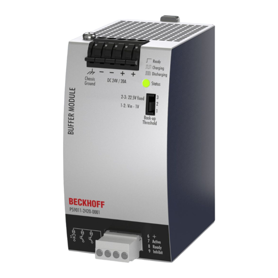
Technical data, application notes, wiring 4.15 Front side and operating elements Fig. 17: Front PS9011-2420-0001 Supply voltage terminals (quick-connect spring-loaded terminals) Designation (A) Description Positive supply voltage terminal (2x) Negative (back) supply voltage terminal (2x) Chassis ground terminal (quick-connect spring-loaded terminal) -
Page 22: Emc
According to IEC 60068-2-27 3 impacts/direction, 18 impacts in total The shock and vibration test takes place in combination with DIN rails according to EN 60715 with a height of 15 mm and a thickness of 1.3 mm and standard orientation. Version: 1.0 PS9011-2420-0001... -
Page 23: Protective Functions And Safety Features
Fig. 18: Dielectric strength Type test 500 Vac 500 Vac 500 Vac Component test 500 Vac 500 Vac 500 Vac Field test 500 Vac 500 Vac 500 Vac Settings for the field test cut-off > 1 mA > 1 mA > 1 mA current PS9011-2420-0001 Version: 1.0... -
Page 24: Declaration Of Conformity And Approvals
Trade conformity assessment for England, Scotland and Wales The UKCA mark indicates conformity with the UK Statutory Instruments 2016 No. 1101 (LVD) 2016 No. 1091 (EMC) and 2012 No. 3032 (RoHS) UL Certificate: UL508, Applicable for US and Canada Version: 1.0 PS9011-2420-0001... -
Page 25: Dimensions And Weight
Housing: Aluminum alloy Cover: galvanized steel Ingress protection Small parts such as screws, nuts, etc. with a diameter greater than 3.5 mm Installation clearances See chapter on Safety instructions and installation requirements [} 8] Fig. 19: PS9011-2420-0001 – front/side view PS9011-2420-0001 Version: 1.0... -
Page 26: Appendix
For lateral DIN rail mounting, the previously removed aluminum brackets and the black plastic slider must be mounted on the steel bracket. Fig. 21: Isometric view, wall mounting dimensioning, installation dimensions of the brackets for lateral mounting Version: 1.0 PS9011-2420-0001... -
Page 27: Documentation Issue Status
Appendix Documentation issue status Version Comment - Corrections and addenda public issue - Corrections and addenda - Preliminary documentation for PS9011-2420-0001 PS9011-2420-0001 Version: 1.0... -
Page 28: Support And Service
Please contact your Beckhoff branch office or representative for local support and service on Beckhoff products! The addresses of Beckhoff's branch offices and representatives round the world can be found on her internet pages: www.beckhoff.com You will also find further documentation for Beckhoff components there. - Page 30 More Information: www.beckhoff.com/ps9011-2420-0001 Beckhoff Automation GmbH & Co. KG Hülshorstweg 20 33415 Verl Germany Phone: +49 5246 9630 info@beckhoff.com www.beckhoff.com...
Need help?
Do you have a question about the PS9011-2420-0001 and is the answer not in the manual?
Questions and answers