Table of Contents
Advertisement
Quick Links
BOCK
HG88e (HC/LG)
®
Operating guide
HG(X)88e/2400-4 (S)
HG(X)88e/2735-4 (S)
HG(X)88e/3235-4 (S)
HGX88e/2400 ML 60 LG
HGX88e/2735 ML 70 LG
HGX88e/3235 ML 80 LG
Translation of the original instructions
HG88e/2400-4 (S) HC
HG88e/2735-4 (S) HC
HG88e/3235-4 (S) HC
HGX88e/2400 S 70 LG
HGX88e/2735 S 80 LG
HGX88e/3235 S 95 LG
AQ451337713574en-000401
Advertisement
Table of Contents

Related Manuals for Danfoss BOCK HG88e


Summary of Contents for Danfoss BOCK HG88e
- Page 1 BOCK HG88e (HC/LG) ® Operating guide HG(X)88e/2400-4 (S) HG88e/2400-4 (S) HC HG(X)88e/2735-4 (S) HG88e/2735-4 (S) HC HG(X)88e/3235-4 (S) HG88e/3235-4 (S) HC HGX88e/2400 ML 60 LG HGX88e/2400 S 70 LG HGX88e/2735 ML 70 LG HGX88e/2735 S 80 LG HGX88e/3235 ML 80 LG HGX88e/3235 S 95 LG Translation of the original instructions AQ451337713574en-000401...
-
Page 2: Table Of Contents
6.3 Pipe connections 6.4 Pipes 6.5 Start unloader (external) 6.6 Laying suction and pressure lines 6.7 Operating the shut-off valves 6.8 Operating mode of the lockable service connections 6.9 Suction pipe filter and filter drier © Danfoss | Climate Solutions | 2023.10 2 | AQ451337713574en-000401... - Page 3 9.3 Spare parts recommendation 9.4 Lubricants / oil 9.5 Decommissioning 9.6 Additional information when using flammable refrigerants 10 Accessories 10.1 Capacity regulator 10.2 Oil separator 10.3 Oil level regulator 11 Technical data 12 Dimensions and connections 13 Declaration of incorporation © Danfoss | Climate Solutions | 2023.10 AQ451337713574en-000401 | 3...
-
Page 4: Safety
As well as professions with comparable training, which enables personnel to assemble, install, maintain and repair refrigeration and air-conditioning systems. Personnel must be capable of assessing the work to be carried out and recognising any potential dangers. © Danfoss | Climate Solutions | 2023.10 4 | AQ451337713574en-000401... -
Page 5: Intended Use
The compressors are intended for use in refrigeration systems in compliance with the limits of application. Only the refrigerant specified in these instructions may be used. Any other use of the compressor is prohibited! © Danfoss | Climate Solutions | 2023.10 AQ451337713574en-000401 | 5... -
Page 6: Safety Instructions For Use Of Flammable Refrigerants
If necessary, a classification of the hazardous areas according to EN60079-10-1 should be carried out. If the refriger- ant concentration exceeds the value of 25% of the lower flamma- bility limit (LEL), all equipment in the hazardous area which is not permitted for operation in hazardous areas must be immediately switched off without any voltage. • Use only suitable equipment approved for flammable refrigerants. • Observe the national regulations. Semi-hermetic compressors are to be classified as "technically INFO tight" (see e.g. TRBS 2152 part 2 / TRGS 722). 2.2 Qualifications required of personnel WARNING Inadequately qualified personnel poses the risk of accidents, the consequence being serious or fatal injury. Work on compressors is therefore reserved for personnel which is qualified in handling flammable refrigerants. © Danfoss | Climate Solutions | 2023.10 6 | AQ451337713574en-000401... -
Page 7: Product Description
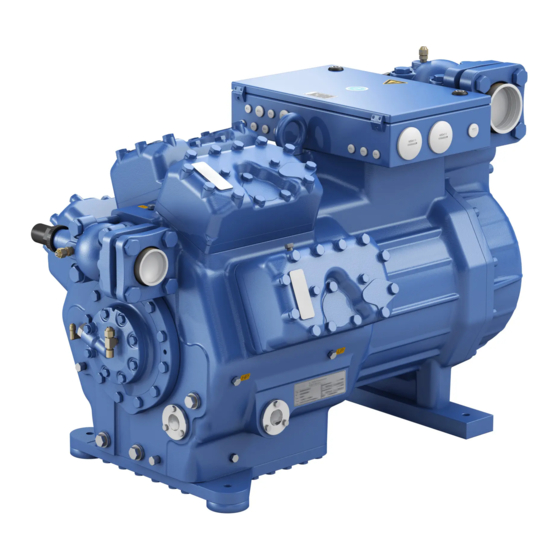
Transport eyelet Cylinder cover Valve plate Discharge shut-off valve Oil pump Name plate Oil sight glasses Fig. 1 Dimension and connection values can be found in Chapter 12 © Danfoss | Climate Solutions | 2023.10 AQ451337713574en-000401 | 7... -
Page 8: Type Key Lg Compressors
HG - Hermetic Gas-Cooled (suction gas-cooled) for the normal- / air conditioning applications ² X - Ester oil charge (HFC refrigerant, e.g. R134a, R404A/R507, R407C, R407F) S - More powerful motor, e.g. for air-conditioning applications © Danfoss | Climate Solutions | 2023.10 8 | AQ451337713574en-000401... -
Page 9: I Ru
Oil filling ² Series ¹ ¹ HG - Hermetic Gas-Cooled (suction gas-cooled) ² X - Ester oil charge S - More powerful motor ML - Motor for normal cooling and deep freezing © Danfoss | Climate Solutions | 2023.10 AQ451337713574en-000401 | 9... -
Page 10: Refrigerants
- T he maximum current and power consumption must not be exceeded. In the case of operation above the mains frequency, the application limit can therefore be limited. Max. 60 Hz. (For more on the frequency converter, see chapter 7.13, p. 27) W hen operating in the vacuum range, there is a danger of air e ntering on the suction side. This can cause chemical reactions, a pressure rise in the condenser and an elevated compressed-gas temperature. Prevent the ingress of air at all costs! © Danfoss | Climate Solutions | 2023.10 10 | AQ451337713574en-000401... -
Page 11: Areas Of Application On Hc And Lg Compressors
During operation in the vacuum range, there is a danger of air entering on the suction side. This can cause chemical reactions, pressure rise in the condenser and an excessive pressure gas tem- perature as well as shifting of the refrigerant ignition limit into the critical range. Avoid absolutely any entry of air! Use a low pressure switch! Select a shut-off point min. 50 Pa higher than the prevailing surrounding pressure! Maximum admissible Maximum admissible operating LP = Low pressure frequency: 60 Hz pressure (LP/HP) : 19/32 bar HP = High pressure © Danfoss | Climate Solutions | 2023.10 AQ451337713574en-000401 | 11... -
Page 12: Compressor Assembly
Do not use in a corrosive, dusty, damp atmosphere or a com- bustible environment. Setup on an even surface or frame with sufficient load-bearing capacity. Single compressor preferably on vibration damper. Duplex and parallel circuits always rigid. On shell and tube condensers, install only with rubber-metal shock mountings. Installation of pipe vibration mufflers is recommended! © Danfoss | Climate Solutions | 2023.10 12 | AQ451337713574en-000401... -
Page 13: Pipe Connections
As soon as the motor and the compressor reach their rated speed, the solenoid valve closes and the non-return valve opens (Fig. 6). The compressor now works under normal load. Solenoid valve actuated Non-return valve closed Fig. 5 © Danfoss | Climate Solutions | 2023.10 AQ451337713574en-000401 | 13... -
Page 14: Laying Suction And Pressure Lines
Proper layout of the suction and discharge lines directly after the compressor is integral to the system’s smooth running and vibration behaviour. A rule of thumb: Always lay the first pipe section starting from the shut-off valve downwards and parallel to the drive shaft. Rigid As short as fixed point Fig. 7 possible © Danfoss | Climate Solutions | 2023.10 14 | AQ451337713574en-000401... -
Page 15: Operating The Shut-Off Valves
Fig. 11 Opening the service connection Spindle: Turn 1 / 2 - 1 turn clockwise. —> Service connection opened / shut-off valve opened. After activating the spindle, generally fit the spindle protection cap again and tighten with 14-16 Nm. This serves as a second sealing feature during operation. © Danfoss | Climate Solutions | 2023.10 AQ451337713574en-000401 | 15... -
Page 16: Suction Pipe Filter And Filter Drier
For motor protection use a current-dependent and time-delayed overload protection device for moni- toring all three phases. Set the overload protection device so that it must be actuated within 2 hours, if there is 1.2 times the max. working current. © Danfoss | Climate Solutions | 2023.10 16 | AQ451337713574en-000401... -
Page 17: Standard Motor, Design For Direct Or Partial Winding Start
Motor für den Direktstart bei annung geschaltet. Für den Stern- rer Spannung geschaltet. Für den Stern- uf bei niederer Spannung sind die eck-Anlauf bei niederer Spannung sind die ntfernen. ken zu entfernen. © Danfoss | Climate Solutions | 2023.10 AQ451337713574en-000401 | 17... - Page 18 Release switch (thermostat) DELTA-P II Oil differential pressure sensor DELTA-P II (accessories) Datum 20.02.2009 Oil sump heater Bearb. bauknecht Compressor motor Gepr. 03.11.2020 Οnderung Datum Name Norm Urspr. Ers. f. Ers. d. © Danfoss | Climate Solutions | 2023.10 18 | AQ451337713574en-000401...
- Page 19 Delay relay for contactor switch over Main switch Mains contactor (part winding 1) Mains contactor (part winding 2) PW INT69 HG88 Control voltage switch Terminal strip in the external switch cabinet BOCK COMPRESSORS © Danfoss | Climate Solutions | 2023.10 AQ451337713574en-000401 | 19...
-
Page 20: Special Motor: Design For Direct Or Star-Delta Start
Designation on the name plate Sticker on the terminal box ∆ / Y ∆ / Y Stern-Dreieck-Anlauf ist nur im Spannungsbereich ∆ (230 V) möglich. Beispiel: 230 V ∆ 400 V Y Direktstart Stern-Dreieck-Start nur Direktstart © Danfoss | Climate Solutions | 2023.10 20 | AQ451337713574en-000401... - Page 21 Direct start only Direct start Star-delta-start In the factory the motor is wired for direct starting at high voltage. The brides are to be removed for star delta starting at low voltage. © Danfoss | Climate Solutions | 2023.10 AQ451337713574en-000401 | 21...
- Page 22 Release switch (thermostat) DELTA-P II Oil differential pressure sensor DELTA-P II (accessories) Datum 20.02.2009 Oil sump heater Bearb. bauknecht Gepr. 03.11.2020 Compressor motor Οnderung Datum Name Norm Urspr. Ers. f. Ers. d. © Danfoss | Climate Solutions | 2023.10 22 | AQ451337713574en-000401...
- Page 23 Control power circuit fuse INT69 G Electronic trigger unit INT69 G Delay relay for contactor switch over Main switch Mains contactor Δ-contactor D/S INT69 HG88 Y-contactor Control voltage switch BOCK COMPRESSORS © Danfoss | Climate Solutions | 2023.10 AQ451337713574en-000401 | 23...
-
Page 24: Electronic Trigger Unit Int69 G
7.7 Connection of the trigger unit INT69 G INFO Connect the trigger unit INT69 G in accordance with the circuit dia- gram. Protect the trigger unit with a delayed-action fuse (F) of max. 4 A. In order to guarantee the protection function, install the trigger unit as the first element in the control power circuit. ATTENTION Motor Protection INT69 G PTC cable on the trigger unit INT69 G and terminals PTC 1 and PTC 2 on the compressor termi- nal board must not come into B1 B2 12 14 11 contact with mains voltage. This would destroy the trigger Lock out unit INT69 G and PTC sensors. supply Abb. 14 Terminal box © Danfoss | Climate Solutions | 2023.10 24 | AQ451337713574en-000401... -
Page 25: Electronic Trigger Unit Int69 G On Hc And Lg Compressors
Cold conductor (PTC sensor) motor winding 10 11 12 14 20 21 Heat protection thermo- stat (PTC sensor) Oil temperature sensor Oil sump heater BT.3 Fig. 16 DELTA- P II © Danfoss | Climate Solutions | 2023.10 AQ451337713574en-000401 | 25... -
Page 26: Oil Sump Heater (Accessories)
7.12 Capacity regulator (Accessories) ATTENTION A fuse (max. 3xlB in accordance with IEC 60127-2-1) corresponding to the rated current must be placed in front of every magnetic coil of the capacity regulator as short-circuit protection. The ra- ted voltage of the fuse must be equal to or greater than the rated voltage of the magnetic coil. The ability of the fuses to switch off must be greater than or equal to the maximum assumable short- circuit current at the installation location. Capacity regulator DCR14 is not approved for digital capacity regulation for HC and LG compressors. © Danfoss | Climate Solutions | 2023.10 26 | AQ451337713574en-000401... -
Page 27: Selection And Operation Of Compressors With Frequency Converters
The compressor has been tested in the factory for pressure integrity. If however the entire system is to be subjected to a pressure integrity test, this should be carried out in accordance with EN 378-2 or a corresponding safety standard without the inclusion of the compressor. © Danfoss | Climate Solutions | 2023.10 AQ451337713574en-000401 | 27... -
Page 28: Leak Test
If the refrigerant needs topping up after starting the compressor, it can be topped up in vapour form on the suction side, or, taking suitable precautions, also in liquid form at the inlet to the evaporator. ATTENTION Avoid overfilling the system with refrigerant! To avoid shifts in concentration, zeotropic refrigerant blends must always only be filled into the refrigerating plant in liquid form. Do not pour liquid coolant through the suction line valve on the compressor. It is not permissible to mix additives with the oil and refrigerant. © Danfoss | Climate Solutions | 2023.10 28 | AQ451337713574en-000401... -
Page 29: Start-Up
Suction gas superheat at the compressor input should be min. 7 - 10 K. (check the setting of the expansion valve). For HC and LG compressors see chapter 5.3. The system must reach a state of equilibrium. Particularly in critical systems (e.g. several evaporator points), measures are recommended such as replacement of liquid traps, solenoid valve in the liquid line, etc. There should be no movement of coolant whatsoever while the compressor is at a standstill. The use of a check valve is strongly recommended, especially for heat pump applications. Otherwise there is a risk of back condensation, which can cause compressor damage. © Danfoss | Climate Solutions | 2023.10 AQ451337713574en-000401 | 29... -
Page 30: Preparation
(e.g. R134a, R407C, R404A) BOCK lub E55 HFO (e.g. R1234yf, BOCK lub E85 (ab t > 15 °C) R1234ze, R455A, R454C) BOCK lub A46 HCFC (e.g. R22) BOCK lub G68 HC (e.g. R290) © Danfoss | Climate Solutions | 2023.10 30 | AQ451337713574en-000401... -
Page 31: Decommissioning
(max. 0.5 bar) and sealed gas-tight. 10 | Accessories 10.1 Capacity regulator ATTENTION If the capacity regulator is installed at the factory, the control com- ponent (pilot valve) is subsequently installed and connected by the customer. LR 1 LR 2 LR 3 Delivery condition 1 (from the factory): Fig. 19 Fig. 18 Cylinder cover prepared for capacity regulator. © Danfoss | Climate Solutions | 2023.10 AQ451337713574en-000401 | 31... - Page 32 W e recommend switching to unregulated operation (100 % capac- ity) for at least 5 minutes per capacity-regulated operating hour. An assured oil return can also be realised by a 100 % capacity requirement after each compressor restart. © Danfoss | Climate Solutions | 2023.10 32 | AQ451337713574en-000401...
-
Page 33: Oil Separator
3-Loch-Anschlussbild für ESK, Mechanical oil level regulator 3 hole connection diagram for AC&R und CARLY ESK, AC&R and CARLY at the "O" connection 3-Loch-Anschlussbild für TraxOil 3 hole diagram for TraxOil © Danfoss | Climate Solutions | 2023.10 AQ451337713574en-000401 | 33... -
Page 34: Technical Data
380-420 V Y/YY - 3 - 50 Hz PW 440-480 V Y/YY - 3 - 60 Hz PW Voltage PW = Part Winding Winding ratio : 50 % / 50 % Displacement (1450 / 1740 rpm) No. of cylinders Type* HG88e/ © Danfoss | Climate Solutions | 2023.10 34 | AQ451337713574en-000401... -
Page 35: Dimensions And Connections
Maß / Dimension Passung / Clearance Änd.-Nr. / Mod-No. Datum / Date Bearb. / Edited Geprüft / Appr. of the grant of a patent, utility model or design. Fig. 25 © Danfoss | Climate Solutions | 2023.10 AQ451337713574en-000401 | 35... - Page 36 8 “ NPTF Connection oil level regulator 3 x M6 ÖV Connection oil service valve 4 “ NPTF Connection oil differential pressure sensor M20x1,5 Connection oil temperature sensor 8 “ NPTF © Danfoss | Climate Solutions | 2023.10 36 | AQ451337713574en-000401...
-
Page 37: Declaration Of Incorporation
Bock GmbH Authorized person for compiling and handing Alexander Layh over technical documentation: Benzstraße 7 72636 Frickenhausen, Germany Frickenhausen, 04th of January 2021 i. A. Alexander Layh, Global Head of R&D © Danfoss | Climate Solutions | 2023.10 AQ451337713574en-000401 | 37... - Page 38 Bock GmbH Authorized person for compiling and handing Alexander Layh over technical documentation: Benzstraße 7 72636 Frickenhausen, Germany Frickenhausen, 14th of October 2022 i. A. Alexander Layh, Global Head of R&D © Danfoss | Climate Solutions | 2023.10 38 | AQ451337713574en-000401...
- Page 39 © Danfoss | Climate Solutions | 2023.10 AQ451337713574en-000401 | 39...
- Page 40 © Danfoss | Climate Solutions | 2023.10 40 | AQ451337713574en-000401...
Need help?
Do you have a question about the BOCK HG88e and is the answer not in the manual?
Questions and answers