
Related Manuals for Danfoss BOCK HRX CO2 T H


Summary of Contents for Danfoss BOCK HRX CO2 T H
- Page 1 BOCK HRX CO ® (transcritical) Operating guide HRX40-2 CO 2 T H HRX60-2 CO 2 T H Translation of the original instructions AQ452531257528en-000201...
- Page 2 Observe the safety instructions contained in these instructions. These instructions must be passed onto the end customer along with the unit in which the compres- sor is installed. © Danfoss | Climate Solutions | 2023.06 2 | AQ452531257528en-000201...
-
Page 3: Table Of Contents
6.9 Filter dryer Maintenance 7.1 Preparation 7.2 Work to be carried out 7.3 Spare parts recommendation 7.4 Lubricants / oil 7.5 Decommissioning Technical data Dimensions and connections Declaration of incorporation © Danfoss | Climate Solutions | 2023.06 AQ452531257528en-000201 | 3... -
Page 4: Safety
As well as professions with comparable training, which enable personnel to assemble, install, maintain and repair refrigeration and air-conditioning systems. Personnel must be capable of assessing the work to be carried out and recognising any potential dangers. © Danfoss | Climate Solutions | 2023.06 4 | AQ452531257528en-000201... -
Page 5: General Safety Instructions
The compressors are intended for use with CO in transcritical systems in compliance with the limits of application. Only the refrigerant specified in these instructions may be used. Any other use of the compressor is prohibited! © Danfoss | Climate Solutions | 2023.06 AQ452531257528en-000201 | 5... -
Page 6: Product Description
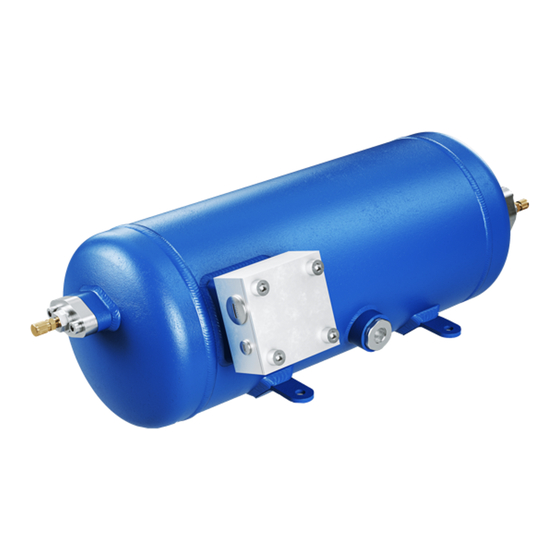
(without shut-off valves). Name plate Terminal box Connection Oil sight glass Fig. 1 Transport eyelet Transport eyelet Connection Fig. 2 Dimension and connection values can be found in chapter 9. © Danfoss | Climate Solutions | 2023.06 6 | AQ452531257528en-000201... -
Page 7: Type Key
Transcritical version Number of poles Swept volume Oil charge ² Series ¹ ¹ HR - Hermetic Radial Gas-Cooled (suction gas-cooled) ² X - Ester oil charge ³ H - Horizontal © Danfoss | Climate Solutions | 2023.06 AQ452531257528en-000201 | 7... -
Page 8: Areas Of Application
- The maximum current and power consumption of the compressor strictly may not be exceeded. The information on the name plate refers to 400 V - 50 Hz (or 460 V - 60 Hz) in mains operation. © Danfoss | Climate Solutions | 2023.06 8 | AQ452531257528en-000201... - Page 9 = HRX40=75 Hz, HRX60=65 Hz 12,5 Hz - 75 Hz HRX40 Rotational speed range 0 - 12,5 Hz 12,5 Hz- 65 Hz HRX60 Start-up time < 1 s Switch-off time instantaneously © Danfoss | Climate Solutions | 2023.06 AQ452531257528en-000201 | 9...
- Page 10 Unlimited application range LP = Low pressure at a drive frequency of 25 - 75 Hz HP = High pressure Unlimited application range at a drive frequency of 25 - 50 Hz © Danfoss | Climate Solutions | 2023.06 10 | AQ452531257528en-000201...
- Page 11 Unlimited application range LP = Low pressure at a drive frequency of 35 - 65 Hz HP = High pressure Unlimited application range at a drive frequency of 50 Hz © Danfoss | Climate Solutions | 2023.06 AQ452531257528en-000201 | 11...
-
Page 12: Compressor Assembly
Setup on an even surface or frame with sufficient load-bearing capacity. Single compressor preferably on vibration damper. Compound connection basically rigid. Recommended mounting position for bus application (roof instal- lation).The compressor should be attached transversely to the driving direction. © Danfoss | Climate Solutions | 2023.06 12 | AQ452531257528en-000201... -
Page 13: Maximum Permissible Inclination
Subsequently verify tightening torque of 37 Nm for screw (1) and then for screw (2). ATTENTION The beaded steel gasket has to be installed without any oil and may be used only once! © Danfoss | Climate Solutions | 2023.06 AQ452531257528en-000201 | 13... -
Page 14: Pipes
A rule of thumb: Always lay the first pipe section starting from the shut-off valve downwards and parallel to the drive shaft. Rigid fixed point As short as possible Fig. 8 © Danfoss | Climate Solutions | 2023.06 14 | AQ452531257528en-000201... -
Page 15: Electrical Connection 15 Gb
1.2 times the maximum working current. 5.2 Connecting the drive motor The compressor is equipped with a motor suitable for direct starting. Sticker on the terminal box 400 V Y L1 L2 © Danfoss | Climate Solutions | 2023.06 AQ452531257528en-000201 | 15... - Page 16 Protection switch motor power circuit Control power circuit fuse BP1 / BP2 High pressure safety monitor / Safety chain (high/low pressure monitoring ) Main switch Compressor contactor Compressor motor Control voltage switch © Danfoss | Climate Solutions | 2023.06 16 | AQ452531257528en-000201...
- Page 17 P> © Danfoss | Climate Solutions | 2023.06 AQ452531257528en-000201 | 17...
-
Page 18: Commissioning
2. Apply the test pressure to the high pressure side while maintaining the test pressure to the low pressure side Exclusively dry test gases may be used for the leak test, e.g. nitrogen N2 min 4.6 (= purity 99.996 % or higher). © Danfoss | Climate Solutions | 2023.06 18 | AQ452531257528en-000201... -
Page 19: Evacuation
ATTENTION Avoid overfilling the machine with refrigerant! Do not charge liquid refrigerant into the suction-side on the compressor. Do not mix additives with the oil and refrigerant. © Danfoss | Climate Solutions | 2023.06 AQ452531257528en-000201 | 19... -
Page 20: Start-Up
For this reason we recom- mend the use of an adequately sized filter drier and a sight glass with a moisture indicator. © Danfoss | Climate Solutions | 2023.06 20 | AQ452531257528en-000201... -
Page 21: Maintenance
The compressor does not possess neither shut-off valves nor decompression valves. These remain within the plant. * Please note that the legacy BOCK code numbers are without 097B © Danfoss | Climate Solutions | 2023.06 AQ452531257528en-000201 | 21... -
Page 22: Technical Data
Max. operating current 380-420 V Y - 3 - 50 Hz Voltage 440-480 V Y - 3 - 60 Hz Displacement 50/60 Hz (2900/3480 rpm No. of cylinders Type © Danfoss | Climate Solutions | 2023.06 22 | AQ452531257528en-000201... -
Page 23: Dimensions And Connections
Unbemaßte Radien / Undimensioned radii: Base part, Raw part: Indication of surface texture über / above DIN EN ISO 1302 1000 bis / up to © Danfoss | Climate Solutions | 2023.06 AQ452531257528en-000201 | 23 ±0.1 ±0.2 ±0.3 ±0.5 ±0.8 11500 27.08.21... -
Page 24: Declaration Of Incorporation
Bock GmbH Authorized person for compiling and handing Alexander Layh over technical documentation: Benzstraße 7 72636 Frickenhausen, Germany Frickenhausen, 04th of January 2021 i. A. Alexander Layh, Global Head of R&D © Danfoss | Climate Solutions | 2023.06 24 | AQ452531257528en-000201... - Page 25 Bock GmbH Authorized person for compiling and handing Alexander Layh over technical documentation: Benzstraße 7 72636 Frickenhausen, Germany Frickenhausen, 14th of October 2022 i. A. Alexander Layh, Global Head of R&D © Danfoss | Climate Solutions | 2023.06 AQ452531257528en-000201 | 25...
- Page 26 © Danfoss | Climate Solutions | 2023.06 26 | AQ452531257528en-000201...
- Page 27 © Danfoss | Climate Solutions | 2023.06 AQ452531257528en-000201 | 27...
- Page 28 © Danfoss | Climate Solutions | 2023.06 28 | AQ452531257528en-000201...
Need help?
Do you have a question about the BOCK HRX CO2 T H and is the answer not in the manual?
Questions and answers