Table of Contents
Advertisement
Quick Links
HG 44 e/HG 5 6e (HC/LG)
BOCK
®
Operating guide
HG(X)44e/475-4 (S)
HG(X)44e/565-4 (S)
HG(X)44e/665-4 (S)
HG(X)44e/770-4 (S)
HG44e/475-4 (S) HC ............................... HG44e/770-4 (S) HC
HG56e/850-4 (S) HC ............................. HG56e/1155-4 (S) HC
HGX44e/475 (S/ML) 9 LG ................. HGX44e/770 (S/ML) 22 LG
HGX56e/850 (S/ML) 18 LG ............. HGX56e/1155 (S/ML) 35 LG
Translation of the original instructions
HG(X)56e/850-4 (S)
HG(X)56e/995-4 (S)
HG(X)56e/1155-4 (S)
AQ452044031215en-000201
Advertisement
Table of Contents

Related Manuals for Danfoss BOCK HG44e


Summary of Contents for Danfoss BOCK HG44e
- Page 1 HG 44 e/HG 5 6e (HC/LG) BOCK ® Operating guide HG(X)44e/475-4 (S) HG(X)56e/850-4 (S) HG(X)44e/565-4 (S) HG(X)56e/995-4 (S) HG(X)44e/665-4 (S) HG(X)56e/1155-4 (S) HG(X)44e/770-4 (S) HG44e/475-4 (S) HC ....... HG44e/770-4 (S) HC HG56e/850-4 (S) HC ......HG56e/1155-4 (S) HC HGX44e/475 (S/ML) 9 LG ....HGX44e/770 (S/ML) 22 LG HGX56e/850 (S/ML) 18 LG .....
-
Page 2: Table Of Contents
1.2 Qualifications required of personnel 1.3 General safety instructions 1.4 Intended use Safety instructions for use of flammable refrigerants 2.1 Safety instructions 2.2 Qualifications required of personnel Product description 3.1 Short description 3.2 Name plate 3.3 Type key 3.4 Type key HC compressors 3.5 Type key LG compressors Areas of application 4.1 Refrigerants 4.2 Oil charge 4.3 Limits of application © Danfoss | Climate Solutions | 2023.06 2 | AQ452044031215en-000201... - Page 3 8.5 Refrigerant charge 8.6 Start-up 8.7 Avoid slugging 8.8 Connection of oil level regulator Maintenance 9.1 Preparation 9.2 Work to be carried out 9.3 Spare parts recommendation / Accessories 9.4 Lubricants / oil 9.5 Decommissioning 9.6 Additional information when using flammable refrigerants 10 Accessories 10.1 Capacity regulator 11 Technical data 12 Dimensions and connections 13 Declaration of incorporation © Danfoss | Climate Solutions | 2023.06 AQ452044031215en-000201 | 3...
-
Page 4: Safety
• F or example, a refrigeration technician, refrigeration mechatronic engineer. As well as professions with comparable training, which enables personnel to assemble, install, maintain and repair refrigeration and air-conditioning systems. Personnel must be capable of assessing the work to be carried out and recognising any potential dangers. © Danfoss | Climate Solutions | 2023.06 4 | AQ452044031215en-000201... -
Page 5: General Safety Instructions
These assembly instructions describe the standard version of the compressor named in the title manufactured by Bock. Bock refrigerating compressors are intended for installation in a machine (within the EU according to the EU Directives 2006/42/EC Machinery Directive, 2014/68/EU Pressure Equipment Directive). Commissioning is permissible only if the compressor has been installed in accordance with these as- sembly instructions and the entire system into which it is integrated has been inspected and approved in accordance with legal regulations. The compressors are intended for use in refrigeration systems in compliance with the limits of application. Only the refrigerant specified in these instructions may be used. Any other use of the compressor is prohibited! © Danfoss | Climate Solutions | 2023.06 AQ452044031215en-000201 | 5... -
Page 6: Safety Instructions For Use Of Flammable Refrigerants
If necessary, a classification of the hazardous areas according to EN60079-10-1 should be carried out. If the refriger- ant concentration exceeds the value of 25% of the lower flamma- bility limit (LEL), all equipment in the hazardous area which is not permitted for operation in hazardous areas must be immediately switched off without any voltage. • Use only suitable equipment approved for flammable refrigerants. • Observe the national regulations. Semi-hermetic compressors are to be classified as "technically INFO tight" (see e.g. TRBS 2152 part 2 / TRGS 722). 2.2 Qualifications required of personnel WARNING Inadequately qualified personnel poses the risk of accidents, the consequence being serious or fatal injury. Work on compressors is therefore reserved for personnel which is qualified in handling flammable refrigerants. © Danfoss | Climate Solutions | 2023.06 6 | AQ452044031215en-000201... -
Page 7: Product Description
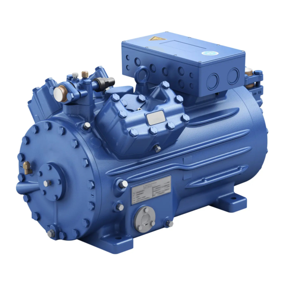
3| Product description 3.1 Short description • HG44e: Semi-hermetic four-cylinder reciprocating compressor with suction-gas cooled drive motor. • HG56e: Semi-hermetic six-cylinder reciprocating compressor with suction-gas cooled drive motor. • Preferred application range: normal refrigerating and air-conditioning. Terminal box Transport eyelet Valve plate Cylinder cover Oil pump Name plate Oil sight glass Fig. 1 HG44e Discharge shut-off valve Suction shut-off valve Drive section Motor section Fig. 2 HG56e Dimension and connection values can be found in Chapter 12 © Danfoss | Climate Solutions | 2023.06 AQ452044031215en-000201 | 7... -
Page 8: Type Key
(g) High pressure side Observe the limits of application diagrams! 3.3 Type key (example) 4 e 770- 4 S Motor variant Number of poles Swept volume e-series (optimized efficiency) Numbers of cylinders Size Oil charge ² Series ¹ ¹ HG - Hermetic Gas-Cooled (suction gas-cooled) ² X - Ester oil charge (HFC refrigerant, e.g. R134a, R404A/R507, R407C, R407F) S - More powerful motor, e.g. for air-conditioning applications © Danfoss | Climate Solutions | 2023.06 8 | AQ452044031215en-000201... -
Page 9: Type Key Hc Compressors
¹ HG - Hermetic Gas-Cooled (suction gas-cooled) ² S - More powerful motor 3.5 Typ key LG compressor (example) Low-GWP Engine performance in hp Motor variant Swept volume e-series Numbers of cylinders Size Oil filling ² Series ¹ ¹ HG - Hermetic Gas-Cooled (suction gas-cooled) ² X - Ester oil charge 3) S - More powerful motor ML - Motor for normal cooling and deep freezing © Danfoss | Climate Solutions | 2023.06 AQ452044031215en-000201 | 9... -
Page 10: Areas Of Application
- When the capacity regulator is activated, the gas velocity in the system can not under certain circumstances ensure that suffi- cient oil is transported back to the compressor. For operation with frequency converter: - T he maximum current and power consumption must not be exceeded. In the case of operation above the mains frequency, the application limit can therefore be limited. (For more on the subject of frequency converters, see chapter 7.13, p. 27) © Danfoss | Climate Solutions | 2023.06 10 | AQ452044031215en-000201... - Page 11 ATTENTION When operating in the vacuum range, there is a danger of air e ntering on the suction side. This can cause chemical reactions, a pressure rise in the condenser and an elevated compressed-gas temperature. Prevent the ingress of air at all costs! Maximum admissible LP = Low pressure operating pressure (g) HP = High pressure (LP/HP) : 19/28 bar © Danfoss | Climate Solutions | 2023.06 AQ452044031215en-000201 | 11...
-
Page 12: Areas Of Application On Hc And Lg Compressors
During operation in the vacuum range, there is a danger of air entering on the suction side. This can cause chemical reactions, pressure rise in the condenser and an excessive pressure gas tem- perature as well as shifting of the refrigerant ignition limit into the critical range. Avoid absolutely any entry of air! Use a low pressure switch! Select a shut-off point min. 50 Pa higher than the prevailing surrounding pressure! Maximum permissible operating LP = Low pressure HP = High pressure pressure (LP/HP) : 19/32 bar © Danfoss | Climate Solutions | 2023.06 12 | AQ452044031215en-000201... -
Page 13: Compressor Assembly
Check the compressor for transport damage before starting any work. 6.1 Storage and transport Storage at (-30°C) - (+70°C), maximum permissible relative humidity 10% - 95%, no condensation Do not store in a corrosive, dusty, vaporous atmosphere or in a com- bustible environment. Use transport eyelet. Do not lift manually! Use lifting gear! 6.2 Setting up ATTENTION Attachments (e.g. pipe holders, additional units, fastening parts, etc.) directly to the compressor are not permissible! Provide adequate clearance for maintenance work. Ensure adequate compressor ventilation. Do not use in a corrosive, dusty, damp atmosphere or a combustible environment. Setup on an even surface or frame with sufficient load- bearing capacity. Single compressor preferably on vibration damper. Duplex and parallel circuits always rigid. Sun protection: If the compressor is set up outdoors, it has to be protected from direct sunlight. © Danfoss | Climate Solutions | 2023.06 AQ452044031215en-000201 | 13... -
Page 14: Pipe Connections
Ensure a proper oil return. Keep pressure losses to an absolute minimum. 6.5 Laying suction and pressure lines ATTENTION Improperly installed pipes can cause cracks and tears, the result being a loss of refrigerant. INFO Proper layout of the suction and discharge lines directly after the compressor is integral to the system’s smooth running and vibration behaviour. © Danfoss | Climate Solutions | 2023.06 14 | AQ452044031215en-000201... -
Page 15: Operating The Shut-Off Valves
6 | Compressor assembly A rule of thumb: Always lay the first pipe section starting from the shut-off valve downwards and parallel to the drive shaft. Rigid As short as fixed point possible Fig. 6 a) For HG44e a intermediate flange (height 27 mm) is optional available, Art-Nr. 097B81194*. With this intermediate flange it is possible to lay the pressure line directly from the valve to the left or right. * Please note that the legacy BOCK ref. numbers are without 097B. 6.6 Operating the shut-off valves Before opening or closing the shut-off valve, release the valve spindle seal by approx. ¼ of a turn counter-clockwise. After activating the shut-off valve, re-tighten the adjustable valve spindle seal clockwise. Tighten Release Valve spindle seal Fig. 7 Fig. 8 © Danfoss | Climate Solutions | 2023.06 AQ452044031215en-000201 | 15... -
Page 16: Operating Mode Of The Lockable Service Connections
For systems with long pipes and higher degree of contamination, a filter on the suction-side is recommended. The filter has to be be renewed depending on the degree of contamination (reduced pressure loss). Moisture in the refrigeration circuit can lead to crystal and hydrate formation. For this reason, we recommend using a filter drier and a sight glass with a moisture indicator. © Danfoss | Climate Solutions | 2023.06 16 | AQ452044031215en-000201... -
Page 17: Electrical Connection
INFO Connect the compressor motor in accordance with the circuit diagram (see inside of terminal box). Use suitable cable entry point of the correct protection type (see name plate) for routing cables into the terminal box. Insert the strain reliefs and prevent chafe marks on the cables. Compare the voltage and frequency values with the data for the mains power supply. Only connect the motor if these values are the same. 7.1 Information for contactor and motor contactor selection All protection equipment, switching and monitoring devices must comply with the local safety regula- tions and established specifications (e.g. VDE) and regulations as well as the manufacturer’s speci- fications. Motor protection switches are required! Motor contactors, feed lines, fuses and motor protection switches must be rated according to the maximum operating current (see name plate). For motor protection, use a current-independent, time-delayed overload protection device for monitor- ing all three phases. Adjust the overload protection device so that it must be actuated within 2 hours at 1.2 times the maximum working current. 7.2 Standard motor, design for direct or part winding start Designation on the name plate Y/YY Compressors with this marking are suitable for direct or partial winding start. The motor winding is subdivided into two parts: Part winding 1 = 50% and part winding 2 = 50%. This winding division reduces the start-up current needed for a part winding start to approx. 50% of that for a direct start. INFO A mechanical unloaded start with bypass solenoid valve is not required. © Danfoss | Climate Solutions | 2023.06 AQ452044031215en-000201 | 17... - Page 18 Anschlußkasten Verdichter Compressor terminal box Fig. 11 High pressure safety monitor Safety chain (high/low pressure monitoring ) Cold conductor (PTC sensor) motor winding Thermal protection thermostat (PTC sensor) Oil temperature sensor Release switch (thermostat) Datum 20.02.2009 DELTA-P II Oil differential pressure sensor DELTA-P II (accessorie) Bearb. bauknecht Gepr. 26.11.2020 Oil sump heater Οnderung Datum Name Norm Urspr. Ers. f. Ers. d. Compressor motor © Danfoss | Climate Solutions | 2023.06 18 | AQ452044031215en-000201...
- Page 19 INT69 G at HC and LG compressors has to be installed outside any Θ danger area! DELTA- P II See also chapter 7.9. Θ FC1.1/1.2 Motor protection switch Control power circuit fuse INT69 G Electronic trigger unit INT69 G Delay relay for contactor switchover Main switch Mains contactor (part winding 1) PW INT69 HG44/66 Mains contactor (part winding 2) BOCK COMPRESSORS Control voltage switch © Danfoss | Climate Solutions | 2023.06 AQ452044031215en-000201 | 19...
- Page 20 7 | Electrical connection The motor is wired for direct start (YY) at the factory. For part winding start Y / YY, the bridges must be removed and the motor feed line connected according to the circuit diagram: 400 V Direktstart YY Teilwicklungsstart Y/YY Direct start YY Part winding start Y/YY ATTENTION Failure to do this results in opposed rotary fields and results in damage to the motor. After the motor starts up via partial winding 1, partial winding 2 must be switched on after a maximum delay of one second . Failure to comply can adversely affect the service life of the motor. © Danfoss | Climate Solutions | 2023.06 20 | AQ452044031215en-000201...
-
Page 21: Special Motor: Design For Direct Or Star-Delta Start
230 V ∆ 400 V Y 230 V ∆ 400 V Y 400 V Y 400 V Y Direct start Direktstart Stern-Dreieck-Start Star-delta start Direct start only Direktstart Stern-Dreieck-Start nur Direktstart Direktstart Stern-Dreieck-Start nur Direktstart nur Direktstart © Danfoss | Climate Solutions | 2023.06 AQ452044031215en-000201 | 21... -
Page 22: Basic Circuit Diagram For Star-Delta Start With Special Motor
Anschlußkasten Verdichter Fig. 12 High pressure safety monitor Safety chain (high/low pressure monitoring ) Cold conductor (PTC sensor) motor winding Thermal protection thermostat (PTC sensor) Oil temperature sensor Release switch (thermostat) Datum 20.02.2009 DELTA PII Oil differential pressure sensor DELTA-P II (accessorie) Bearb. bauknecht Oil sump heater Gepr. 03.11.2020 Οnderung Datum Name Norm Urspr. Ers. f. Ers. d. Compressor motor © Danfoss | Climate Solutions | 2023.06 22 | AQ452044031215en-000201... -
Page 23: Electronic Trigger Unit Int69 G
Θ installed outside any danger area! See also chapter 7.9. DELTA- P II Θ FC1.1/1.2 Motor protection switch Control power circuit fuse INT69 G Electronic trigger unit INT69 G Delay relay for contactor switchover Main switch Mains contactor D/S INT69 HG44/66 neu Δ-contactor Y-contactor BOCK COMPRESSORS Control voltage switch © Danfoss | Climate Solutions | 2023.06 AQ452044031215en-000201 | 23... - Page 24 (PTC sensor) must not come into contact with external voltage. B1 B2 This would destroy the trigger unit INT69 G and PTC sensors. N 43 43 11 X2 1 Θ Θ Θ Steuerstrom- Steuerstrom- Control circuit kreis kreis Θ Fig. 13 Terminal box © Danfoss | Climate Solutions | 2023.06 24 | AQ452044031215en-000201...
-
Page 25: Electronic Trigger Unit Int69 G On Hc And Lg Compressors
11-12 Reset after mains on 11-14 7.9 Electronic trigger unit INT69 G at HC and LG compressors The supplied INT69 G must be connected according to the wiring diagram shown here in a separate control cabinet, which must be installed outside each danger zone. ATTENTION Install heat protection thermostats and cold conductor motor winding in series! Schaltschrank Switch cabinet INT69G Cold conductor (PTC sensor) motor winding 10 11 12 13 20 21 Heat protection thermo- stat (PTC sensor) Oil temperature sensor BT.3 Oil sump heater DELTA- P II Fig. 15 © Danfoss | Climate Solutions | 2023.06 AQ452044031215en-000201 | 25... -
Page 26: Oil Sump Heater On Hc And Lg Compressors
As the solubility of hydrocarbons and HFO refrigerants in oil can be very high, especially at high suction pressures, the compressor must be equipped with an oil sump heater. For this reason, a pump-down circuit is recommended during standstill to reduce the suction-side standstill pressures. ATTENTION The oil sump heater must generally be connected and operated! • In a TT- or TN system, a residual current protection device (RCD) must be used. • In an IT system, an insulation monitoring device must be used. National standards and regulations must be observed. © Danfoss | Climate Solutions | 2023.06 26 | AQ452044031215en-000201... -
Page 27: Capacity Regulator (Accessories)
Capacity regulator DCR14 is not approved for digital capacity regulation for HC and LG compressors. 7.13 Selection and operation of compressors with frequency converters For safe operation of the compressor, the frequency converter must be able to apply an overload of at least 140% of the compressor's maximum current (I-max.) for at least 3 seconds. When using frequency converters, the following things must also be observed: 1. The maximum permissible operating current of the compressor (I-max) (see type plate or technical data) must not be exceeded. 2. If abnormal vibrations occur in the system, the affected frequency ranges in the frequency converter must be blanked out accordingly. 3. The maximum output current of the frequency converter must be greater than the maximum current of the compressor (I-max). 4. Carry out all designs and installations in accordance with the local safety regulations and common rules (e.g. VDE) and regulations as well as in accordance with the specifications of the frequency converter manufacturer The permissible frequency range can be found in the technical data chapter 11, p. 35/36. Rotational speed 0 - f-min f-min - f-max range Start-up time < 1 s ca. 4 s immediately Switch-off time f-min/f-max see chapter 11: Technical data: permissible frequency range © Danfoss | Climate Solutions | 2023.06 AQ452044031215en-000201 | 27... -
Page 28: Commissioning
Do not mix any refrigerant with the nitrogen as this could cause the ignition limit to shift into the critical range. C arry out the leak test on the refrigerating plant in accordance with EN 378-2 or a corresponding safety standard, while always observing the maximum permissible overpressure for the compressor. 8.4 Evacuation ATTENTION Do not start the compressor if it is under vacuum. Do not apply any voltage - even for test purposes (must only be operated with r efrigerant). Under vacuum, the spark-over and creepage current distances of the terminal board connection bolts shorten; this can result in winding and terminal board damage. First evacuate the system and then include the compressor in the evacuation process. Relieve the compressor pressure. Open the suction and pressure line shut-off valves. Evacuate the suction and discharge pressure sides using the vacuum pump. At the end of the evacuation process, the vacuum should be < 1.5 mbar when the pump is switched off. Repeat this process as often as is required. For HC and LG compressors suitable equipment approved for flammable refrigerants must be used. © Danfoss | Climate Solutions | 2023.06 28 | AQ452044031215en-000201... -
Page 29: Refrigerant Charge
If the refrigerant needs topping up after starting the compressor, it can be topped up in vapour form on the suction side, or, taking suitable precautions, also in liquid form at the inlet to the evaporator. ATTENTION Avoid overfilling the system with refrigerant! To avoid shifts in concentration, zeotropic refrigerant blends must always only be filled into the refrigerating plant in liquid form. Do not pour liquid coolant through the suction line valve on the compressor. It is not permissible to mix additives with the oil and refrigerant. 8.6 Start-up WARNING Ensure that both shut-off valves are open before starting the compressor! Check that the safety and protection devices (pressure switch, motor protection, electrical contact protection measures, etc.) are all functioning properly. Switch on the compressor and allow to run for a minimum of 10 min. Check the oil level by: The oil must be visible in the sightglass. ATTENTION I f larger quantities of oil have to be topped up, there is a risk of oil hammer effects. If this is the case check the oil return! © Danfoss | Climate Solutions | 2023.06 AQ452044031215en-000201 | 29... -
Page 30: Connection Of Oil Level Regulator
Adapter angeschlossen werden (s. Abb.). Ein Schauglas am Ölspiegelregulator ist nicht erforderlich. Fig. 17 47,6 3-Loch-Anschlussbild für ESK, 3 hole connection diagramm for Mechanical oil level regulator AC&R und CARLY ESK, AC&R and CARLY at the "O" connection 3-Loch-Anschlussbild für TraxOil 3 hole diagramm for TraxOil ahr von © Danfoss | Climate Solutions | 2023.06 30 | AQ452044031215en-000201... -
Page 31: Maintenance
Annual checks: Oil level, leak tightness, running noises, pressures, temperatures, function of a uxiliary devices such as oil sump heater, pressure switch. 9.3 Spare parts recommendation/accessories Available spare parts and accessories can be found on our compressor selection tool under vap.bock.de as well as at bockshop.bock.de. Only use genuine Bock spare parts! © Danfoss | Climate Solutions | 2023.06 AQ452044031215en-000201 | 31... -
Page 32: Lubricants / Oil
• If the compressor is to be removed from the system for maintenance or repair, the remaining refrigerant must be suctioned out and the compressor evacuated. The compressor must then be filled with nitrogen (max. 0.5 bar) and sealed gas-tight. © Danfoss | Climate Solutions | 2023.06 32 | AQ452044031215en-000201... -
Page 33: Accessories
CR 2 Fig. 18 HG44e HG56e Fig. 19 Fig. 20 Delivery condition 1 (from the factory): Before commissioning, the blind flange with Cylinder cover prepared for capacity regulator. screws must be removed and replaced by the new set capacity regulator with O-ring joints and screws. Observe position and construction of the capacity regulator. Attention! Compressor is under pressure! Depressurize the compressor first. Fig. 21 Delivery condition 2 (from the factory): Connect capacity regulator in terminal box or switch cabinet. © Danfoss | Climate Solutions | 2023.06 AQ452044031215en-000201 | 33... - Page 34 Continuous operation in the control stage is not recommended as the gas velocity in the plant system under certain circumstances does not guarantee sufficient oil return to the compressor with activated capacity regulator. W e recommend switching to unregulated operation (100% capac- ity) for at least 5 minutes per capacity-regulated operating hour. An assured oil return can also be realised by a 100% capacity requirement after each compressor restart. E lectrical actuation of the solenoid valve: Normally open, (cor- responds to 100 % compressor capacity). Special accessories are only premounted in the factory if ordered specially by customer. Retrofitting is possible in full compliance with the safety instructions and repair instructions enclosed with the kits. Information about the use, operation, maintenance and servicing of the components is available in the printed literature or on the internet under www.bock.de. For the capacity regulator a step protection is optional available, Art-Nr. 097B81449*. * Please note that the legacy BOCK ref. numbers are without 097B. Fig. 22 © Danfoss | Climate Solutions | 2023.06 34 | AQ452044031215en-000201...
-
Page 35: Technical Data
Oil charge (ex works) Suction line Discharge line Weight permissible fre- 25 - 70 quency range Starting current (rotor locked) Max. power consumption Max. operating current 380-420 V Y/YY - 3 - 50 Hz PW 440-480 V Y/YY - 3 - 60 Hz PW Voltage PW = Part Winding Winding ratio : 50 % / 50 % Displacement (1450 / 1740 rpm) No. of cylinders Type* HG44e/ © Danfoss | Climate Solutions | 2023.06 AQ452044031215en-000201 | 35... - Page 36 Oil charge (ex works) Suction line Discharge line Weight permissible fre- 25 - 70 quency range Starting current (rotor locked) Max. power consumption Max. operating current 380-420 V Y/YY - 3 - 50 Hz PW 440-480 V Y/YY - 3 - 60 Hz PW Voltage PW = Part Winding Winding ratio : 50 % / 50 % Displacement (1450 / 1740 rpm) No. of cylinders Type* HG56e/ © Danfoss | Climate Solutions | 2023.06 36 | AQ452044031215en-000201...
-
Page 37: Dimensions And Connections
Maß / Dimension Passung / Clearance of the grant of a patent, utility model or design. Oil strainer M12 x 1,5 Connection oil level regulator 3 x M6 Connection oil differential pressure sensor M20 x 1,5 Connection oil temperature sensor 8 “ NPTF Connection for refrigerant injection 8 “ NPTF © Danfoss | Climate Solutions | 2023.06 AQ452044031215en-000201 | 37... - Page 38 Gußtoleranzen / General casting tolerances: Zeichnungs-Nr. / Teile-Nr. / Blatt / Maßstab / Drawing-No. Part-No. Page: Scale: © Danfoss | Climate Solutions | 2023.06 38 | AQ452044031215en-000201 Baumustergeprüft / Type examination: 0850 14937 .0 Nein / No Gewicht / Weight: (kg)
-
Page 39: Declaration Of Incorporation
Bock GmbH Authorized person for compiling and handing Alexander Layh over technical documentation: Benzstraße 7 72636 Frickenhausen, Germany Frickenhausen, 04th of January 2021 i. A. Alexander Layh, Global Head of R&D © Danfoss | Climate Solutions | 2023.06 AQ452044031215en-000201 | 39... - Page 40 UKCA Experts Ltd. over technical documentation: Dept 302, 43 Owston Road Carcroft, Doncaster, DN6 8DA, United Kingdom Frickenhausen, 14th of October 2022 i. A. Alexander Layh, Global Head of R&D © Danfoss | Climate Solutions | 2023.06 40 | AQ452044031215en-000201...
- Page 41 © Danfoss | Climate Solutions | 2023.06 AQ452044031215en-000201 | 41...
- Page 42 © Danfoss | Climate Solutions | 2023.06 42 | AQ452044031215en-000201...
Need help?
Do you have a question about the BOCK HG44e and is the answer not in the manual?
Questions and answers