Table of Contents
Advertisement
Quick Links
HG 44 e/HG 5 6e
®
BOCK
Operating guide
HG44e/475-4
HG44e/565-4
HG44e/665-4
HG44e/770-4
HG56e/850-4
HG56e/995-4
HG56e/1155-4
Translation of the original instructions
HG44e/475-4 S
HG44e/565-4 S
HG44e/665-4 S
HG44e/770-4 S
HG56e/850-4 S
HG56e/995-4 S
HG56e/1155-4 S
HGX44e/475-4
HGX44e/565-4
HGX44e/665-4
HGX44e/770-4
HGX56e/850-4
HGX56e/995-4
HGX56e/1155-4
HGX44e/475-4 S
HGX44e/565-4 S
HGX44e/665-4 S
HGX44e/770-4 S
HGX56e/850-4 S
HGX56e/995-4 S
HGX56e/1155-4 S
AQ451925859810en-000301
Advertisement
Table of Contents

Subscribe to Our Youtube Channel
Related Manuals for Danfoss BOCK HG44e Series


Summary of Contents for Danfoss BOCK HG44e Series
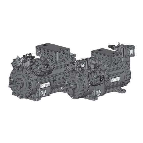
- Page 1 HG 44 e/HG 5 6e ® BOCK Operating guide HG44e/475-4 HG44e/475-4 S HGX44e/475-4 HGX44e/475-4 S HG44e/565-4 HG44e/565-4 S HGX44e/565-4 HGX44e/565-4 S HG44e/665-4 HG44e/665-4 S HGX44e/665-4 HGX44e/665-4 S HG44e/770-4 HG44e/770-4 S HGX44e/770-4 HGX44e/770-4 S HG56e/850-4 HG56e/850-4 S HGX56e/850-4 HGX56e/850-4 S HG56e/995-4 HG56e/995-4 S HGX56e/995-4 HGX56e/995-4 S HG56e/1155-4 HG56e/1155-4 S HGX56e/1155-4 HGX56e/1155-4 S Translation of the original instructions AQ451925859810en-000301...
-
Page 2: Table Of Contents
Electrical connection 5.1 Information for contactor and motor contactor selection 5.2 Standard motor, design for direct or partial winding start 5.3 Basic circuit diagram for partial winding start with standard motor 5.4 Special motor: design for direct or star-delta start 5.5 Basic circuit diagram for star-delta start with special motor 5.6 Electronic trigger unit INT69 G 5.7 Connecting of the trigger unit INT69 G 5.8 Functional test of the trigger unit INT69 G 5.9 Oil sump heater (accessories) 5.10 Selection and operation of compressors with frequency converters 2 | AQ451925859810en-000301 © Danfoss | Climate Solutions | 2024.07... - Page 3 6.6 Start-up 6.7 Avoid slugging 6.8 Connection of oil level regulator Maintenance 7.1 Preparation 7.2 Work to be carried out 7.3 Condensate drainage 7.4 Spare parts recommendation/accessories 7.5 Lubricants / oils 7.6 Decommissioning Accessories 8.1 Capacity regulator Technical data Dimensions and connections Declaration of incorporation AQ451925859810en-000301 | 3 © Danfoss | Climate Solutions | 2024.07...
-
Page 4: Safety
• F or example, a refrigeration technician, refrigeration mechatronic engineer. As well as professions with comparable training, which enables personnel to assemble, install, maintain and repair refrigeration and air-conditioning systems. Personnel must be capable of assessing the work to be carried out and recognising any potential dangers. 4 | AQ451925859810en-000301 © Danfoss | Climate Solutions | 2024.07... -
Page 5: General Safety Instructions
These assembly instructions describe the standard version of the compressor named in the title manufactured by Bock. Bock refrigerating compressors are intended for installation in a machine (within the EU according to the EU Directives 2006/42/EC Machinery Directive, 2014/68/EU Pressure Equipment Directive). Commissioning is permissible only if the compressor has been installed in accordance with these as- sembly instructions and the entire system into which it is integrated has been inspected and approved in accordance with legal regulations. The compressors are intended for use in refrigeration systems in compliance with the limits of application. Only the refrigerant specified in these instructions may be used. Any other use of the compressor is prohibited! AQ451925859810en-000301 | 5 © Danfoss | Climate Solutions | 2024.07... -
Page 6: Product Description
2.1 Short description • HG44e: Semi-hermetic four-cylinder reciprocating compressor with suction-gas cooled drive motor. • HG56e: Semi-hermetic six-cylinder reciprocating compressor with suction-gas cooled drive motor. • Preferred application range: normal refrigerating and air-conditioning. Terminal box Transport eyelet Valve plate Cylinder cover Oil pump Name plate Oil sight glass Fig. 1 HG44e Discharge shut-off valve Suction shut-off valve Drive section Motor section HG56e Fig. 2 Dimension and connection values can be found in Chapter 10 6 | AQ451925859810en-000301 © Danfoss | Climate Solutions | 2024.07... - Page 7 Observe the limits of application diagrams! 2.3 Type key (example) 4 e 770- 4 S Motor variant Number of poles Swept volume e-series (optimized efficiency) Numbers of cylinders Size Oil charge ² Series ¹ HG - Hermetic Gas-Cooled (suction gas-cooled) ¹ X - Ester oil charge (HFC refrigerant, e.g. R134a, R404A/R507, R407C, R407F) ² S - More powerful motor, e.g. for air-conditioning applications AQ451925859810en-000301 | 7 © Danfoss | Climate Solutions | 2024.07...
-
Page 8: F 3 Areas Of Application
- The maximum current and power consumption must not be exceeded. In the case of operation above the mains frequency, the application limit can therefore be limited. (For more on the subject of frequency converters, see chapter 5.10, p. 24) 8 | AQ451925859810en-000301 © Danfoss | Climate Solutions | 2024.07... - Page 9 Prevent the ingress of air at all costs! LP = Low pressure Maximum admissible HP = High pressure operating pressure (g) (LP/HP) : 19/28 bar AQ451925859810en-000301 | 9 © Danfoss | Climate Solutions | 2024.07...
-
Page 10: Compressor Assembly
4.2 Setting up ATTENTION Attachments (e.g. pipe holders, additional units, fastening parts, etc.) directly to the compressor are not permissible! Provide adequate clearance for maintenance work. Ensure adequate compressor ventilation. Do not use in a corrosive, dusty, damp atmosphere or a combustible environment. Setup on an even surface or frame with sufficient load- bearing capacity. Single compressor preferably on vibration damper. Duplex and parallel circuits always rigid. Sun protection: If the compressor is set up outdoors, it has to be protected from direct sunlight. 10 | AQ451925859810en-000301 © Danfoss | Climate Solutions | 2024.07... -
Page 11: Pipe Connections
ATTENTION Improperly installed pipes can cause cracks and tears, the result being a loss of refrigerant. INFO Proper layout of the suction and discharge lines directly after the compressor is integral to the system’s smooth running and vibration behaviour. AQ451925859810en-000301 | 11 © Danfoss | Climate Solutions | 2024.07... -
Page 12: Operating The Shut-Off Valves
Rigid As short as fixed point possible Fig. 6 a) For HG44e a intermediate flange (height 27 mm) is optional available, Art-Nr. *097B81194. With this intermediate flange it is possible to lay the pressure line directly from the valve to the left or right. * Please note that the legacy BOCK code numbers without 097B 4.6 Operating the shut-off valves Before opening or closing the shut-off valve, release the valve spindle seal by approx. ¼ of a turn counter-clockwise. After activating the shut-off valve, re-tighten the adjustable valve spindle seal clockwise. Tighten Release Valve spindle seal Fig. 7 Fig. 8 12 | AQ451925859810en-000301 © Danfoss | Climate Solutions | 2024.07... -
Page 13: Operating Mode Of The Lockable Service Connections
For systems with long pipes and higher degree of contamination, a filter on the suction-side is recommended. The filter has to be be renewed depending on the degree of contamination (reduced pressure loss). Moisture in the refrigeration circuit can lead to crystal and hydrate formation. For this reason, we recommend using a filter drier and a sight glass with a moisture indicator. AQ451925859810en-000301 | 13 © Danfoss | Climate Solutions | 2024.07... -
Page 14: Electrical Connection
Use suitable cable entry point of the correct protection type (see name plate) for routing cables into the terminal box. Insert the strain reliefs and prevent chafe marks on the cables. Compare the voltage and frequency values with the data for the mains power supply. Only connect the motor if these values are the same. 5.1 Information for contactor and motor contactor selection All protection equipment, switching and monitoring devices must comply with the local safety regula- tions and established specifications (e.g. VDE) and regulations as well as the manufacturer’s speci- fications. Motor protection switches are required! Motor contactors, feed lines, fuses and motor protection switches must be rated according to the maximum operating current (see name plate). For motor protection, use a current-independent, time-delayed overload protection device for monitor- ing all three phases. Adjust the overload protection device so that it must be actuated within 2 hours at 1.2 times the maximum working current. 14 | AQ451925859810en-000301 © Danfoss | Climate Solutions | 2024.07... -
Page 15: Standard Motor, Design For Direct Or Partial Winding Start
5.2 Standard motor, design for direct or part winding start Designation on the name plate Y/YY Compressors with this marking are suitable for direct or partial winding start. The motor winding is subdivided into two parts: Part winding 1 = 50% and part winding 2 = 50%. This winding division reduces the start-up current needed for a part winding start to approx. 50% of that for a direct start. INFO A mechanical unloaded start with bypass solenoid valve is not required. AQ451925859810en-000301 | 15 © Danfoss | Climate Solutions | 2024.07... - Page 16 Anschlußkasten Verdichter Fig. 11 High pressure safety monitor Safety chain (high/low pressure monitoring ) Cold conductor (PTC sensor) motor winding Thermal protection thermostat (PTC sensor) Oil temperature sensor Release switch (thermostat) Datum 20.02.2009 DELTA-P II Oil differential pressure sensor DELTA-P II (accessorie) Bearb. bauknecht Gepr. 26.11.2020 Oil sump heater Οnderung Datum Name Norm Urspr. Ers. f. Ers. d. Compressor motor 16 | AQ451925859810en-000301 © Danfoss | Climate Solutions | 2024.07...
- Page 17 L1.1 L2.1 L3.1 L1.2 P> Θ Θ Θ DELTA- P II Θ FC1.1/1.2 Motor protection switch Control power circuit fuse Electronic trigger unit INT69 G INT69 G Delay relay for contactor switchover Main switch PW INT69 HG44/66 Mains contactor (part winding 1) Mains contactor (part winding 2) BOCK COMPRESSORS Control voltage switch AQ451925859810en-000301 | 17 © Danfoss | Climate Solutions | 2024.07...
- Page 18 After the motor starts up via partial winding 1, partial winding 2 must be switched on after a maximum delay of one second . Failure to comply can adversely affect the service life of the motor. 18 | AQ451925859810en-000301 © Danfoss | Climate Solutions | 2024.07...
-
Page 19: Special Motor: Design For Direct Or Star-Delta Start
∆ ∆ ∆ Star-delta start-up is only possible for 230 V power supply. Example: 230 V ∆ ∆ ∆ ∆ 400 V Y Direct start Star-delta start Direct start only AQ451925859810en-000301 | 19 © Danfoss | Climate Solutions | 2024.07... -
Page 20: Basic Circuit Diagram For Star-Delta Start With Special Motor
Anschlußkasten Verdichter Fig. 12 High pressure safety monitor Safety chain (high/low pressure monitoring ) Cold conductor (PTC sensor) motor winding Thermal protection thermostat (PTC sensor) Oil temperature sensor Release switch (thermostat) Datum 20.02.2009 Bearb. bauknecht DELTA PII Oil differential pressure sensor DELTA-P II (accessorie) Gepr. 03.11.2020 Oil sump heater Οnderung Datum Name Norm Urspr. Ers. f. Ers. d. Compressor motor 20 | AQ451925859810en-000301 © Danfoss | Climate Solutions | 2024.07... - Page 21 L2.1 L3.1 L1.2 P> Θ Θ Θ DELTA- P II Θ FC1.1/1.2 Motor protection switch Control power circuit fuse Electronic trigger unit INT69 G INT69 G Delay relay for contactor switchover Main switch Mains contactor D/S INT69 HG44/66 neu Δ-contactor BOCK COMPRESSORS Y-contactor Control voltage switch AQ451925859810en-000301 | 21 © Danfoss | Climate Solutions | 2024.07...
-
Page 22: Electronic Trigger Unit Int69 G
B1 B2 This would destroy the trigger N 43 43 11 X2 1 unit INT69 G and PTC sensors. Θ Θ Θ Steuerstrom- Steuerstrom- Control circuit kreis kreis Θ Fig. 18 Fig. 13 Terminal box 22 | AQ451925859810en-000301 © Danfoss | Climate Solutions | 2024.07... -
Page 23: Functional Test Of The Trigger Unit Int69 G
11-14 5.9 Oil sump heater When the compressor is at a standstill, refrigerant diffuses into the lubricating oil of the compressors housing, depending on pressure and ambient temperature. This reduces the lubricating capacity of the oil. When the compressor starts up, the refrigerant contained in the oil evaporates out throught the reduction in pressure. The consequences can be foaming and migration of the oil, causing oil shocks under certain circumstances. Operation: The oil sump heater operates when the compressor is at a standstill. When the compres- sor starts up, the oil sump heater switches off again automatically. Connection: The oil sump heater must be connected via an auxiliary contact (or parallel wired auxili- ary contact) of the compressor contactor to a seperate electric circuit. El. data: 230 V - 1 - 50/60 Hz, 160 W. Fig. 15 ATTENTION Connection to the current path of the safety control chain is not permitted. AQ451925859810en-000301 | 23 © Danfoss | Climate Solutions | 2024.07... -
Page 24: Selection And Operation Of Compressors With Frequency Converters
5.10 Selection and operation of compressors with frequency converters For safe operation of the compressor, the frequency converter must be able to apply an overload of at least 140% of the compressor's maximum current (I-max.) for at least 3 seconds. When using frequency converters, the following things must also be observed: 1. The maximum permissible operating current of the compressor (I-max) (see type plate or technical data) must not be exceeded. 2. If abnormal vibrations occur in the system, the affected frequency ranges in the frequency converter must be blanked out accordingly. 3. The maximum output current of the frequency converter must be greater than the maximum current of the compressor (I-max). 4. A fter each compressor start, run for at least 1 minute at a frequency of at least 50 Hz. 5. Carry out all designs and installations in accordance with the local safety regulations and common rules (e.g. VDE) and regulations as well as in accordance with the specifications of the frequency converter manufacturer The permissible frequency range can be found in the technical data. Rotational speed 0 - f-min f-min - f-max range < 1 s ca. 4 s Start-up time immediately Switch-off time f-min/f-max see chapter: Technical data: adjustable frequency range 24 | AQ451925859810en-000301 © Danfoss | Climate Solutions | 2024.07... -
Page 25: Commissioning
Do not start the compressor if it is under vacuum. Do not apply any voltage - even for test purposes (must only be operated with refrigerant). Under vacuum, the spark-over and creepage current distances of the terminal board connection bolts shorten; this can result in winding and terminal board damage. First evacuate the system and then include the compressor in the evacuation process. Relieve the compressor pressure. Open the suction and pressure line shut-off valves. Evacuate the suction and discharge pressure sides using the vacuum pump. At the end of the evacuation process, the vacuum should be < 1.5 mbar when the pump is switched off. Repeat this process as often as is required. AQ451925859810en-000301 | 25 © Danfoss | Climate Solutions | 2024.07... -
Page 26: Refrigerant Charge
Ensure that both shut-off valves are open before starting the compressor! Check that the safety and protection devices (pressure switch, motor protection, electrical contact protection measures, etc.) are all functioning properly. Switch on the compressor and let it run for at least 1 minute at a frequency of at least 50 Hz. Only then may the speed of the compressor be reduced. Check the oil level by: The oil must be visible in the sightglass. ATTENTION I f larger quantities of oil have to be topped up, there is a risk of oil hammer effects. If this is the case check the oil return! 26 | AQ451925859810en-000301 © Danfoss | Climate Solutions | 2024.07... -
Page 27: Connection Of Oil Level Regulator
6.8 Connection of oil level regulator Oil level regulation systems have proven themselves with parallel circuits of several compressors. The connection "0" is provided for installing an oil level regulator (see dimensions drawing). All common oil level regulators from AC&R, ESK and Carly as well as the OM3 TraxOil oil level regulation system from Alco can be connected directly without adapters (see Fig. 16). A sight glass on the oil level regulator is not required. M6 x 10 je 3 mal 3 times each Fig. 16 47,6 3 hole connection diagramm for Mechanical oil level regulator 3-Loch-Anschlussbild für ESK, ESK, AC&R and CARLY AC&R und CARLY at the "O" connection 3 hole diagramm for TraxOil 3-Loch-Anschlussbild für TraxOil AQ451925859810en-000301 | 27 © Danfoss | Climate Solutions | 2024.07... -
Page 28: Maintenance
IP65 to IP32! Condensate drainage Fig. 17 7.4 Spare parts recommendation/accessories Available spare parts and accessories can be found on our compressor selection tool under vap.bock.de as well as at bockshop.bock.de. Only use genuine Bock spare parts! 28 | AQ451925859810en-000301 © Danfoss | Climate Solutions | 2024.07... -
Page 29: Lubricants / Oils
7 | Maintenance 7.5 Lubricants / oil The oil type filled as standard in the factory is marked on the name plate, and this should always be used, even in the case of maintenance units. Alternative oil types can vary significantly in quality due to additives or inferior raw materials by the manufacturer. Validation within the compressors entire operating limits can not be guaranteed, if such alternative oil types are used. It is for this reason, that we only recommend the use of oil from Bock! Bock assumes no liability for any damage arising from alternative oil types. Refrigerants Bock standard oil types HFC (e.g. R134a, R407C, R404A) BOCK lub E55 HCFC (e.g. R22) BOCK lub A46 7.6 Decommissioning Close the shut-off valves on the compressor. Drain the refrigerant (it must not be discharged into the environment) and dispose of it according to the regulations. When the compressor is depressurised, undo the fastening screws of the shut-off valves. Remove the compressor using an appropriate hoist. Dispose of the oil inside in accordance with the applicable national regulations. AQ451925859810en-000301 | 29 © Danfoss | Climate Solutions | 2024.07... -
Page 30: Accessories
Before commissioning, the blind flange with Cylinder cover prepared for capacity regulator. screws must be removed and replaced by the new set capacity regulator with O-ring joints and screws. Observe position and construction of the capacity regulator. Attention! Compressor is under pressure! Depressurize the compressor first. Fig. 21 Delivery condition 2 (from the factory): Connect capacity regulator in terminal box or switch cabinet. 30 | AQ451925859810en-000301 © Danfoss | Climate Solutions | 2024.07... - Page 31 An assured oil return can also be realised by a 100% capacity requirement after each compressor restart. Electrical actuation of the solenoid valve: Normally open, (cor- responds to 100 % compressor capacity). Special accessories are only premounted in the factory if ordered specially by customer. Retrofitting is possible in full compliance with the safety instructions and repair instructions enclosed with the kits. Information about the use, operation, maintenance and servicing of the components is available in the printed literature or on the internet under www.bock.de. For the capacity regulator a step protection is optional available, Art-Nr. *097B81449. * Please note that the legacy BOCK code numbers are without 097B Fig. 22 AQ451925859810en-000301 | 31 © Danfoss | Climate Solutions | 2024.07...
-
Page 32: Technical Data
Adjustable fre- 25 - 70 quency range Starting current (rotor locked) Max. power consumption Max. operating current 380-420 V Y/YY - 3 - 50 Hz PW 440-480 V Y/YY - 3 - 60 Hz PW Voltage PW = Part Winding Winding ratio : 50 % / 50 % Displacement (1450 / 1740 rpm) No. of cylinders Type HG44e/ 32 | AQ451925859810en-000301 © Danfoss | Climate Solutions | 2024.07... - Page 33 Adjustable fre- 25 - 70 quency range Starting current (rotor locked) Max. power consumption Max. operating current 380-420 V Y/YY - 3 - 50 Hz PW 440-480 V Y/YY - 3 - 60 Hz PW Voltage PW = Part Winding Winding ratio : 50 % / 50 % Displacement (1450 / 1740 rpm) No. of cylinders Type HG56e/ AQ451925859810en-000301 | 33 © Danfoss | Climate Solutions | 2024.07...
-
Page 34: Dimensions And Connections
M12 x 1,5 Connection oil level regulator 3 x M6 Connection oil pressure differential sensor M20x1,5 Connection oil temperature sensor 1/8" NPTF Connection for refrigerant injection 8 “ NPTF 34 | AQ451925859810en-000301 © Danfoss | Climate Solutions | 2024.07... - Page 35 Maßstab / Drawing-No. Part-No. Page: Scale: Baumustergeprüft / Type examination: 000D 41147 .0 Nein / No AQ451925859810en-000301 | 35 © Danfoss | Climate Solutions | 2024.07 Gewicht / Weight: (kg) Allgemeintoleranzen / General tolerances Benennung / Description: DIN ISO 2768-mK-E...
-
Page 36: Declaration Of Incorporation 36 D
#3A1, Bommasandra Industrial Area, Hebbagodi, Bock GmbH Hosur Road, Bangalore – 560099 Alexander Layh Benzstraße 7 72636 Frickenhausen, Germany Sivakumar Gopalan, Head - Operations, BOCK India - CC-HP Frickenhausen, 05th of December 2023 36 | AQ451925859810en-000301 © Danfoss | Climate Solutions | 2024.07... - Page 37 #3A1, Bommasandra Industrial Area, Hebbagodi, Danfoss LTD., 22 Wycombe End, Hosur Road, Bangalore – 560099 HP9 1NB, GB Sivakumar Gopalan, Head - Operations, BOCK India - CC-HP Frickenhausen, 05th of December 2023 AQ451925859810en-000301 | 37 © Danfoss | Climate Solutions | 2024.07...
- Page 38 38 | AQ451925859810en-000301 © Danfoss | Climate Solutions | 2024.07...
Need help?
Do you have a question about the BOCK HG44e Series and is the answer not in the manual?
Questions and answers