Table of Contents
Advertisement
INSTRUCTION MANUAL
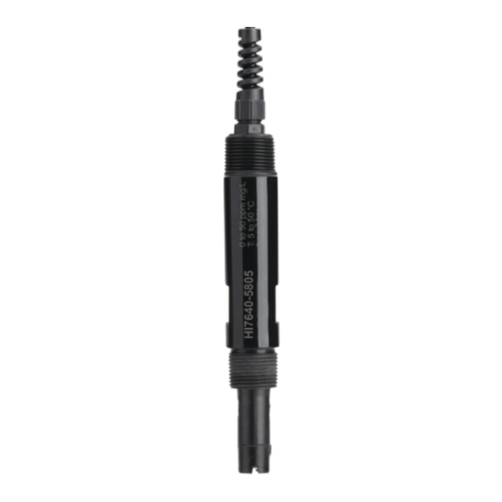
HI7640-58
Optical Dissolved Oxygen
Industrial Smart Probes
HI510 Compatible
®
Hanna
is committed to developing and deploying digital solutions
with a positive impact on the environment and climate.
Please scan the QR code or follow the link
to download the
HI510
https://manuals.hannainst.com/HI510
Hanna Instruments Inc., 584 Park East Drive, Woonsocket, RI 02895 USA
controller user manual.
www.hannainst.com
Advertisement
Table of Contents

Related Manuals for Hanna Instruments HI7640-58


Summary of Contents for Hanna Instruments HI7640-58
- Page 1 Please scan the QR code or follow the link to download the HI510 controller user manual. https://manuals.hannainst.com/HI510 Hanna Instruments Inc., 584 Park East Drive, Woonsocket, RI 02895 USA www.hannainst.com...
-
Page 2: Table Of Contents
All rights are reserved. Reproduction in whole or in part is prohibited without the written consent of the copyright owner, Hanna Instruments Inc., Woonsocket, Rhode Island, 02895, USA. Hanna Instruments reserves the right to modify the design, construction, or appearance of its products without advance notice. -
Page 3: Preliminary Examination
Smart Caps (HI764113-1) for measurement of dissolved oxygen. ® The series is designed to work with the Hanna Instruments HI510 Universal Process Controller. When paired with the controller, the system provides accurate dissolved oxygen measurements auto-compensated for barometric pressure, salinity (set manually), and temperature. -
Page 4: Main Features
Main Features Principle of Operation The method is based on the principle of fluorescence quenching and features an immobilized Pt- based luminophore that is excited by the light of a blue LED and emits a red light. Dissolved oxygen quenches this excitation. -
Page 5: Specifications
5 Specifications 6. SPECIFICATIONS 0.00 to 50.00 mg/L (ppm) concentration Range 0.0 to 500.0 % saturation 0.01 mg/L (ppm) Resolution 0.1 % saturation from 0.00 to 20.00 mg/L (ppm) 1.5 % of reading or ± 0.01 mg/L (ppm), whichever is greater from 20.00 to 50.00 mg/L (ppm) ±5% of reading Accuracy from 0.0 to 200.0 % saturation... -
Page 6: Probe Dimensions & Cable Connection
Probe Dimensions & Cable Connection 7. PROBE DIMENSIONS & CABLE CONNECTION Ø 17 mm (0.7”) 3/4’’ NPT 3/4’’ NPT 43 mm (1.7”) 64 mm (2.5”) 172 mm (6.7”) 172 mm (6.7”) Align the pins and key then push the plug into the socket. Rotate the collar to lock in place. -
Page 7: Installation
Installation 1. Smart Cap 2. Alignment key 2. Sensor body 4. Temperature sensor 5. Embedded O sensitive luminophore with black protective layer DETAIL 6. RFID Tag 7. Optical window 1 Smart Cap 8. O-Ring Seal 2 Alignment key 3 Probe body 4 Temperature sensor Embedded O sensitive luminophore with rugged,... - Page 8 Installation Typical installation examples with mounting accessories Accessories are sold separately. User-assembled, top thread immersion installation 1 Cable gland 2 Pipe cap (socket connect or threaded) 3 Van Stone flange (one size smaller than the pipe) 4 2”, or similar, PVC pipe (schedule 80 PVC) Reducer bushing •...
- Page 9 Installation Flow-cell installation • The circulation pipes from the tank to the flow-cell must be thermally insulated. Avoid temperature differences greater than 2 °C (36 °F) between tank content and flow cell sample. • Shade the assembly from direct sunlight. 1 Process controller 2 Wiring cable 3 Optical DO probe FLOW CELL 4 Flow-cell adapter 5 Flow cell EXIT FLOW 6 Flow-cell valves...
-
Page 10: Wiring The Probe To The Controller
Wiring the Probe to the Controller 10. WIRING THE PROBE TO THE CONTROLLER 1. With the controller disconnected from power, run the probe cable through the conduit opening. 2. Connect the probe leads to the removable terminal connector marked PROBE. Follow the lead markings (+) positive / (–) negative to ensure correct wiring position for output leads. - Page 11 Calibration Standard Calibration Preparation • Remove probe from process. • Flush probe and cap with a jet of clean water. • Inspect for scratches or voids in cap surface. • Replace cap as required. • Shake any remaining solution off the probe. No droplets should remain on the DO sensing surface before performing the calibration procedure.
-
Page 12: Maintenance
Maintenance Process Calibration Prior to performing a process calibration, a reference meter and probe must be used (or another method) to determine DO value of the process. Preparation • Determine the process DO value, using a calibrated reference meter and probe. •... - Page 13 Maintenance Ensure all cap-replacement steps are correctly followed. 1. Prior to cap replacement, verify time and date are correctly set in the controller setup menu. 2. Turn OFF the controller and unplug the removable terminal connector marked PROBE by loosening the four screws and reaching inside the enclosure.
-
Page 14: Accessories
Accessories 13. ACCESSORIES Ordering Information Product Description DO Solutions HI7040L Zero oxygen solution set, 500 mL + 12 g Other Accessories HI60501 PVC immersion electrode holder HI60501-0 O-rings for HI60501 electrode holder HI60501-2 PVC protective end cap, inside height 68 mm (2.6”) HI605011 PVC mounting flange HI764113-1... -
Page 15: Certification
If the repair is not covered by the warranty, you will be notified of the charges incurred. If the instrument is to be returned to Hanna Instruments, first obtain a Returned Goods Authorization (RGA) number from the Technical Service department and then send it with shipping costs prepaid.
Need help?
Do you have a question about the HI7640-58 and is the answer not in the manual?
Questions and answers