Table of Contents
Advertisement
Quick Links
Advertisement
Table of Contents

Subscribe to Our Youtube Channel
Related Manuals for Hanna Instruments HI510


Summary of Contents for Hanna Instruments HI510
- Page 1 HI510 Process Controller...
- Page 2 If you need additional technical information, do not hesitate to e‑mail us at tech@hannainst.com or view our contact list at www.hannainst.com. All rights are reserved. Reproduction in whole or in part is prohibited without the written consent of the copyright owner, Hanna Instruments Inc., Woonsocket, Rhode Island, 02895, USA.
-
Page 3: Table Of Contents
3.2. PROBE SPECIFICATIONS .................... 9 4. GENERAL DESCRIPTION & INTENDED USE ................11 4.1. ADDITIONAL FEATURES ................... 12 5. HI510 MODELS & DEDICATED SMART PROBES ..............14 5.1. CONTROLLER MODELS ..................... 14 5.2. SMART PROBES ...................... 14 6. FUNCTIONAL & DISPLAY DESCRIPTION ................15 6.1. - Page 4 15.4. CLEANING TRIGGERS ................... 111 15.5. STOP CLEANING ....................113 15.6. OVERVIEW OF CLEANING TYPES ................115 16. HI510 EVENTS MANAGEMENT SYSTEM................116 16.1. ALARMS, WARNINGS, ERRORS ................116 17. PROBE CONDITIONING & MAINTENANCE ................ 123 18. TROUBLESHOOTING GUIDE ................... 124 19.
- Page 5 23. ACCESSORIES ....................... 130 23.1. pH CALIBRATION SOLUTIONS ................130 23.2. ORP SOLUTIONS ....................130 23.3. ELECTRODE STORAGE SOLUTIONS ................ 130 23.4. ELECTRODE CLEANING SOLUTIONS ............... 130 23.5. ELECTRODE HOLDERS ..................131 23.6. FLOW CELL & SADDLE FITTINGS ................133 23.7.
- Page 6 About this Manual • This manual contains instructions for installation and operation of the Hanna Instruments HI510 Universal Process Controller. • This release of the product manual contains information that applies to HI510 Process Controller operating with HI10X6-Y8ZZ pH & Temperature or HI20X4-Y8ZZ ORP &...
-
Page 7: Preliminary Examination
1. PRELIMINARY EXAMINATION Remove the instrument and accessories from the packaging and examine it carefully. For further assistance, please contact your local Hanna Instruments Office or email us at tech@hannainst.com. Each HI510 Process Controller is delivered in a cardboard box and is supplied with power cable (3 meters long), a set of cable gland seals, instrument certificate, and instruction manual. -
Page 8: Specifications
3. SPECIFICATIONS 3.1. CONTROLLER SPECIFICATIONS Smart HI10X6 series – pH & Temperature with RS485 interface Digital probes Smart HI20X4 series – ORP & Temperature with RS485 interface Display Graphic LCD, 128 x 64 pixel B/W with backlight 2 independent, galvanically isolated inputs (configurable for Hold Digital inputs &... -
Page 9: Probe Specifications
Weight Approximately 1.6 kg (3.5 lb.) Width 144.0 mm (5.7”) Dimensions Height 144.0 mm (5.7”) Depth 151.3 mm (6.0”) Environment -20 to 50 ºC (-4 to 122 ºF); maximum 100% RH non-condensing 3.2. PROBE SPECIFICATIONS HI1006-1805 pH Digital Probe Range 0.00 to 12.00 pH Temperature -5.0 to 80.0 ºC / 23 to 176 ºF... - Page 10 HI2004-1805 ORP Digital Probe Range -2000 to +2000 mV Temperature -5.0 to 80.0 ºC / 23 to 176 ºF Accuracy ±2 mV Body PVDF Junction PTFE Sensor Platinum ring Sensor tip Flat Maximum pressure 6 bar Probe cable length 5 meters 3/4”...
-
Page 11: General Description & Intended Use
5V up to 24 Vdc digital inputs, and flexible function assignments for relays regarding process control, cleaning or Hold mode. Hanna Instruments dedicated smart probes allow for shared management of settings between controller and probe, where the controller manages only settings related to the intended application, as defined by requirements of the industrial process, and the probe manages settings and warnings related to measurements, including temperature compensation and buffer calibration. -
Page 12: Additional Features
MAIN FEATURES • Smart probes with RS485 connection. Automatic probe recognition PROCESS INPUT and upload of settings configuration and measurement data MENUS • Easily navigable main menu and submenus • Two or four, depending on the controller model, galvanically isolated, ANALOG OUTPUTS (0-20 or 4-20mA) ALARM RELAY... - Page 13 Manual Mode • pH single point process calibration, or calibration up to three-points, using two buffer sets: • Hanna Instruments – 1.68, 4.01, 7.01, 10.01, 12.45 pH • NIST – 1.68, 4.01, 6.86, 9.18, 12.45 pH CALIBRATION • ORP calibration using a single point process calibration •...
-
Page 14: Hi510 Models & Dedicated Smart Probes
5.2. SMART PROBES Hanna Instruments smart probes enable accurate and automated collection of data. The pH and ORP configuration schemes detailed below list all the combination, flat tip, PVDF-body, polymer filled electrodes with matching pin and operating pressure of up to 6 bar (87 psi). -
Page 15: Functional & Display Description
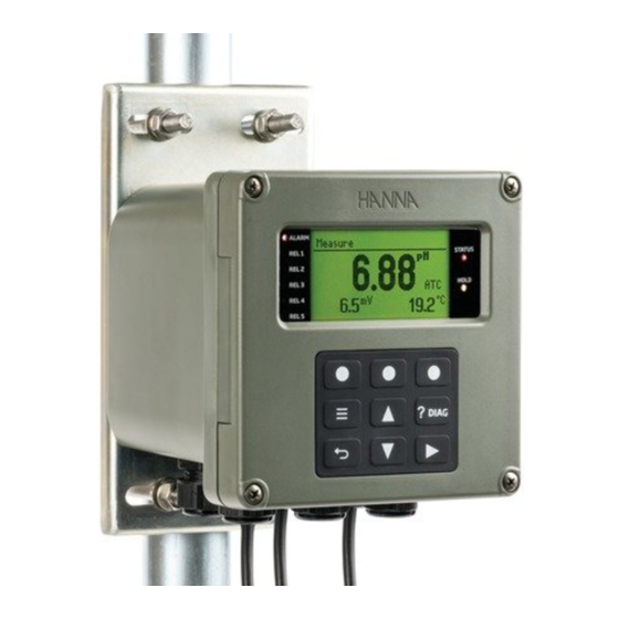
6. FUNCTIONAL & DISPLAY DESCRIPTION 6.1. FRONT PANEL • The front panel includes a graphic display and keypad with tactile feedback. • The first LCD line displays information regarding controller status, the second LCD line displays measurement readings, and the third LCD line displays the temperature value or additional messages. -
Page 16: Main Display Functions
6.2. MAIN DISPLAY FUNCTIONS Title & Status area Main reading display area Main reading value Raw reading area (mV) Warning (!) or Alarm (!!) icon, press ?DIAG key ( ) for description Displayed parameter alarm status (high or low) Temperature Compensation status Temperature reading area Warning icon Virtual key option... -
Page 17: Contextual Help
6.4. CONTEXTUAL HELP • HI510 offers an interactive contextual help mode that assists the user at any time. • To access the help screen, press the diagnostic (?DIAG ) key. The instrument will display additional information related to the current screen. To read all the available information, scroll the text using the keys. -
Page 18: Opening The Enclosure
-s er vi ce N o us er rv ic in g R ef er se ne l. in si de . pe rs on se rv ic e qu al ifi ed Figure 3: HI510 Enclosure Opened Figure 4: Hinged Front Panel... -
Page 19: Installation
7. INSTALLATION 7.1. GENERAL GUIDELINES • HI510 Process Controller is suitable for outdoor use, but installation in direct sunlight or in areas of extreme temperature is not recommended. • Based on controller specifications, installation thermal conditions are in the -20 ºC to 50 ºC (-4 to 122 ºF) range. - Page 20 12mm 0.5” Figure 6: Wall-Mount Panel Thickness, Mounting Bolts & Slots Dimensions The minimum depth required by HI510 fastened to a 12 mm (0.5 “) mounting plate is 163 mm (6.4”). 163mm 6.4” Figure 7: HI510 Controller Fastened to Wall-Mount Panel...
- Page 21 Wall-Mount Hardware & Steps The controller can be mounted on a wall using a wall-mount panel that can be fixed in a horizontal or vertical position. Use the wall-mount panel and appropriate hardware. See table, description column, for details. The mounting kit does not include the fasteners required for attaching the wall-mount panel to the wall.
-
Page 22: Panel Mount
To wall mount the controller: 1. Select the position desired for the controller and following the dimensions indicated in Figure 6, drill the holes required for attaching the wall-mount panel to the surface. The drill size depends on the fasteners dimension required by wall type and thickness. 2. - Page 23 0.2” +0.04 138mm 5.43” 0.00 Figure 10: Panel-Mount Cutout Panel-Mount Hardware & Steps The controller can be mounted in a panel. Use two brackets and appropriate, supplied hardware that includes external gasket and several types of screws. See table, description column, for details. Figure 11: Panel-Mount Schematic...
- Page 24 Panel-Mount Hardware Label Description Quantity Process controller 1 pc. External gasket 1 pc. Panel bracket, 100 mm (3.93”) long 2 pcs. M4 x 45 mm screw (DIN 7985) 4 pcs. Plain washer for M6 screw 4 pcs. Spring washer for M6 screw 4 pcs.
-
Page 25: Pipe Mount
7.4. PIPE MOUNT Pipe-Mount Hardware & Steps The controller can be mounted vertically or horizontally on a pipe. Use a mount plate and U-bolts together with supplied hardware that includes hex nuts and several types of screws. See table, description column, for details. Figure 13: Pipe-Mount Schematic &... - Page 26 Figure 14: Horizontal Pipe Mount Pipe-Mount Hardware Label Description Quantity Process controller 1 pc. Hex nut M8 4 pcs. Mount plate 1 pc. Plain washer for M8 screw 4 pcs. Spring washer M8 screw 4 pcs. Plain washer for M6 screw 4 pcs.
-
Page 27: Wiring The Hi510 Process Controller
8. WIRING THE HI510 PROCESS CONTROLLER 8.1. GENERAL INFORMATION HI510 universal process controller is easy to wire. To access the wiring locations, loosen the four captive screws, on the front of the hinged panel, enough for the springs to push them out. Grasp the front bezel on the right side and swing the bezel open to the left. - Page 28 Assembly drawing of an exposed cable gland, with the seal entering from the external part, and with the parts shown on each side of the enclosure wall Figure 16: Exposed Cable Gland Schematic Label Description Metallic nut Metallic base plate Enclosure wall Cable gland seal Cable gland body...
-
Page 29: Wiring The Controller
8.3. WIRING THE CONTROLLER • Easy access to HI510 installation terminals − push in and plug out − enable quick wiring. • High voltage connections, i.e. power (8), alarm (1) and control relays (7) are made to the Terminal 1 block under cover. - Page 30 Terminal 1 Terminal 2 ALARM CONDITION ALARM METER OFF COMM RELAY 100mA ALARM RELAY 1 RELAY 2 PROBE 100mA RELAY 3 RELAY 4 RELAY 5 5-30V DIGITAL Line POWER INPUTS Protective Earth INPUT Neutral 5-30V 0 - 20 mA OUT / 4 - 20 mA OUT 0 - 20 mA OUT / 4 - 20 mA OUT...
- Page 31 Fail Safe Alarm Feature The controller is equipped with the Fail Safe alarm feature to protect the process against critical errors arising from power interruptions, power surges and human errors. The Fail Safe alarm feature resolves these predicaments on two fronts: hardware and software. Hardware To eliminate problems of blackout and line failure, the alarm function operates in a “Normally Closed”...
-
Page 32: Terminal 2 Wiring
Connect the End Of Line Resistor (EOLR) as required by RS485 bus connection. 4. Feed excess cable through the cable gland before tightening nut. 8.4.3. Digital Input HI510 controller has two digital inputs. Digital input IN1 and IN2 may be used to activate a signaled HOLD and / or a cleaning function. -
Page 33: Display Description
9. DISPLAY DESCRIPTION 9.1. MAIN DISPLAY • The HI510 has a large backlit display that shows pH and Temperature or ORP (mV) and Temperature measurements in large digits. • Screenshots below show examples of the main measurement screen for either the pH & Temperature or ORP &... -
Page 34: Icon Description & Function
Alarm High on the parameter. Displayed next to the reading (e.g. temperature reading), indicates Alarm Low on the parameter. An error symbol asking users to contact Hanna Instruments Technical Support. Indicates the controller is connected to the PC application ... -
Page 35: General Operations
Measure is the normal operating mode of the controller. Depending on the probe wired, and the location of the probe, the display will show measured values with appropriate measurement units. At start-up, while the controller performs internal checks, the display will show the Hanna Instruments logo, controller name, date, and firmware version. -
Page 36: Menu
11. MENU The MENU key ( ) is used to access menus for programming control functions and calibrating the controller. By pressing the key from the live readings display, the menu will open, revealing eight top level parameters, detailed below. Press the arrow keys to navigate through the list. -
Page 37: Channel, Cal
Parameter Screenshot Function MANUAL Enables users to directly drive the relays or analog outputs MODE Enables users access to logged data, file transfer to LOG RECALL USB stick Enables users to configure or view general settings e.g. log interval, password, date and time, language GENERAL selection, setting RS485 communication parameters, setting controller ID... - Page 38 One-, two- or three-point calibration can be performed using one of the buffer solutions selected from one of the two groups: • Hanna Instruments buffers set: 1.68, 4.01, 7.01, 10.01, 12.45 pH • NIST buffers set: 1.68, 4.01, 6.86, 9.18, 12.45 pH...
- Page 39 • At prompt, with the password enabled, input the passcode. • The first suggested buffer solution “7.01 pH” (if using Hanna Instruments buffer group) or “6.86 pH” (if using NIST buffer group) is displayed in the upper left of the display window.
- Page 40 Three-Point • Follow Two-Point calibration steps and press Next when prompted. • Immerse the pH probe in the third calibration buffer. The buffer solution will be recognized and displayed flashing. • When the reading is stable, the buffer value stops flashing and CFM is displayed. Press CFM, to save. •...
- Page 41 • “Wait” is displayed at the bottom of the LCD screen until the calibration point is memorized. • “DONE” confirmation message is displayed for a few seconds. Note: Process calibration evaluates electrode offset. 11.1.1.3. ORP Calibration (ORP Probes) ORP calibration is a single point calibration that can be performed with the probe installed in the process or with the probe removed from the process.
- Page 42 Calibration An ORP calibration is a single point calibration. The calibration point value is displayed, and the value can be adjusted ± 60 mV around the measured mV. If an ORP calibration standard is used, the probe is removed from the process, cleaned off then placed in a beaker with the standard.
- Page 43 11.1.1.5. pH Calibration Messages & Warnings Message Recommended Action Screenshot “Invalid Slope” Verify the probe is in the The electrode slope is outside buffer selected and that the accepted slope limit. buffer is fresh. Calibration can not be confirmed. “Clean Electrode” Clean the probe to improve The offset, evaluated at first the pH electrode's response.
- Page 44 • Press the keys to navigate between parameters. • Select from virtual keys View, Set or Modify. • Press the key to return to the menu without saving. • At prompt, enter the passcode. • At prompt, press YES, to place unit in HOLD. Probe Info (all Probe Types) Option: probe specific Calibration Timeout (all Probe Types)
- Page 45 To obtain the temperature offset, see step 3, Temperature Calibration procedure. Temperature Calibration Steps 1. Place the probe and a reference thermometer (with 0.1° resolution) into a stirred container of water. 2. Observe the temperature on display until it stops changing. This may take several minutes. 3.
- Page 46 Cal. Buffer Group (With pH Probe Only) Option: Hanna, NIST With Cal.BufferGroup selected, press Modify. Use the keys to select between Hanna or NIST buffers. Press CFM, to save selection. CalData To access the CalData display option: • Press Menu while in Measure mode, followed by Channel Setup. The CalData key is displayed. •...
- Page 47 Note: We suggest users make configuration changes from the beginning of the menu structure going forward, because the menu references parameters that were set earlier in the submenu. Navigation • With Control Settings selected, press Setup, to enter the menu. •...
- Page 48 Value This parameter defines the Set point value. With Value selected, press Set. Press the keys to edit the required value within minimum / maximum probe limits (e.g. 0.00 to 12.00 pH), displayed blinking. Press CFM, to save. Mode Option: ON/OFF, Proportional, PID The Mode parameter defines the type of control the controller will use: ON/OFF, Proportional or PID.
- Page 49 Setup for Proportional control • For the drop-down list to be displayed, press Setup. • Press the keys to move between Mode, Deviation, Control Period and Dead Band. • Select Mode and press the virtual keys to choose Prop. Low or Prop. High. •...
- Page 50 • With Dead Band (default value 0.02 pH) highlighted, press Set. The present value will blink permitting editing, within minimum 0.00 pH and maximum Deviation value divided by 5, using keys. • Press CFM, to save • Press the key, to exit Setup. Setup for PID control •...
- Page 51 • Press CFM, to save • Press the key, to select Reset Time. • With Reset Time (default 16:40 h) highlighted, press Set. The present value will blink permitting editing, within minimum 1 minute and maximum 16:40 h, using the keys.
- Page 52 Overtime (Setpoint must be enabled first) Option: Disabled, 10 to 120 minutes The overtime (safety timer) parameter is provided to set the maximum continuous time a relay running a pump or valve is energized. For a control that is running an On/Off algorithm and its output is a relay, this time is the continuous time the relay is On before an alarm is issued.
- Page 53 11.1.4. Alarm Settings This menu is used to define the operating limits of the process. The setting thresholds configured in this submenu control the Alarm relay. If Alarm becomes active, control stops. Both pH (or ORP) and Temperature are configured in this submenu. Navigation •...
- Page 54 The check mark confirms parameter is enabled. Press the key, to save. Alarm High Allows users to set the upper-limit value for the alarm. To modify the value, with Alarm High selected, press Set. The flashing digit indicates that value can be modified.
-
Page 55: Hold Mode
Press Set, to modify the value. The flashing value indicates that it can be modified. Press the keys followed by CFM, to save. Once confirmed, the value stops flashing. Press the key to return to the menu. Delay Off Time Option: 5 to 999 seconds Delay Off Time is an off delay timer. - Page 56 4. The state next to the Menu item will change to Man On (or OFF) 5. Press the key, to exit the parameter When in Manual Hold: • Hold is displayed in the Title & Status area • The primary measurement value is displayed blinking •...
-
Page 57: Outputs
Hold Output This is a read only parameter that indicates what relay outputs (if any) are configured to Hold mode. To return to the menu without changing, press key. Hold Release Delay Option: 0 to 99 seconds Hold Release Delay is a timer that allows control function to remain in a HOLD state for additional time after the HOLD is released. - Page 58 • With Outputs selected, press Setup to open a submenu structure that includes Relays and Analog Outputs. • Press the keys to toggle between them and press Setup, to open the selected parameter. • At prompt, enter the password. • At prompt, with the password enabled, press YES, to place unit in HOLD and start modifying parameters.
- Page 59 Multiple relays can be allocated to the same function. To select the relay operating mode, press Modify. Note: HI510-320 has 3 relays and 2 Analog Outputs (AO) & HI510-540 has 5 relays and 4 Analog Outputs (AO).
- Page 60 • Track Channel – the analog output follows a specific parameter Data Channel Option: CH1 for one channel Data channel is always CH1. Parameter Option: CtrlSetP1, CtrlSetP2, pH or ORP (main probe reading), Temperature With Parameter selected, press Modify and select the parameter from the available options. Press CFM, to save.
- Page 61 With Value at 0mA (or 4mA) selected, press Set. The value will flash indicating it can be modified. Press the keys to increase or decrease the value. Press CFM, to save. Value for 20mA Option: Selected parameter (pH, mV, temperature, ), CtrlSetP1 or CtrlSetP2 With value at 20mA selected, press Set.
-
Page 62: Inputs
With Out 22mA -On Alarm selected press the corresponding virtual key to enable or disable. When enabled, it drives the analog output to 22mA in an alarm condition. Note: The controller validates the configured Setup when attempting to exit Menu and directs the user to any invalid parameters. -
Page 63: Cleaning
For modifying the operating mode for either input please follow the four-step procedure below: 1. With Input 1 (or Input 2) selected, press Setup. 2. Press the keys to navigate between the two possible options. 3. Press Modify, for the Function drop-down list to display. 4. - Page 64 requirements of the particular application. When Advanced cleaning is selected, it is possible to stop a cleaning cycle manually by long pressing (a few seconds) the keys simultaneously. The cleaning is stopped but the cycle will complete the rinse and recovery phases before returning to the measurement or process control. Calibration cannot be started when Simple or Advanced cleaning is in progress.
- Page 65 Enabled* Option: Enabled, Disabled With Enabled selected, press the corresponding virtual key to enable (activate) cleaning mode or disable cleaning mode. Type Option: Simple, Advanced With Cleaning Type selected, press Advanced or Simple, to toggle options. Ext. Trigger Option: None, Input 1, Input 2 This is a read-only parameter that indicates what Input, if any, has been assigned to start cleaning.
- Page 66 Timer When set on Timer, the cleaning cycle will proceed following the time period set in the parameter Cleaning Interval. Schedule If Int. Trigger is selected, options are Disabled or Timer, N/A will be seen. If Int. Trigger is set to Schedule, options are ON or Off. •...
- Page 67 Wash Time Option: 5 to 300 seconds With Wash Time selected, press Set, to modify. The flashing digit can be modified by pressing the keys. Press CFM, to save. Post-Wash Rinse Time Option: 5 to 999 seconds With Post-Wash Rinse Time selected, press Set, to modify. The flashing digit can be modified by pressing the keys.
- Page 68 Recovery Time Option: 1 to 120 seconds Time period for the probe to be reacclimated to the process before starting control. • With Recovery Time selected, press Set. • The flashing digit can be modified by pressing the keys. • Press CFM, to save. Rinse Relay Option: Allows users to display allocated rinse relay This is a view only parameter that indicates what relay(s) are configured for the rinse function.
-
Page 69: Manual Mode
Recovery Time Option: 1 to 120 seconds Rinse Relay Option: Allows users to display allocated rinse relay Note: The controller validates the configured Setup when attempting to exit Menu and directs the user to any invalid parameters. At prompt to save changes, press YES. 11.6. -
Page 70: Log Recall
Relay x Option: On, Off The relay set to be On, keeps its status for maximum 60 minutes before it switches Off; or user leaves Manual Mode. Analog Output AO x Option: 0.0 to 22.0 mA 1. From Manual mode, press the keys to move to AO x. - Page 71 Navigation • From main Menu, press the keys to select Log Recall. • With option selected, press Select, to enter screen. The controller creates a log file for each parameter (pH or ORP). The logged files are saved in parameter specific Lot Log folders. Lot Log •...
- Page 72 • The exported logs will be in a folder named HI510-xxxx (where x are the controller ID) Note: Do not remove the USB flash drive during the file transfer. If an error occurs during transfer, the “Error while transferring” message is displayed. Reinstall the flash drive and try again.
- Page 73 Delete Logged Data To delete logged files: • Press the keys to select the option and press CFM. A warning screen will be displayed asking for confirmation. • Press Yes to confirm or No to return to previous screen. Note: It is recommended to export log files before deleting the files. Event Log &...
- Page 74 Process calibration Hold Cleaning Setup updated Depending on the number of setup changes, users can access more than one screen by pressing the virtual key for -->.
- Page 75 HI510 Log Event Codes & Assigned Parameters HI510 operates an event logging system whereby when setting new parameter values, a Setup event & event code are generated. Log event stores the Setup event code together with both new and previous values.
- Page 76 Code Setup Parameter Code Setup Parameter 124 Cleaning, wash cycles number 187 Analog out 1, data channel 125 Cleaning, rinse only cycles 188 Analog out 2, data channel 131 Cleaning external trigger 189 Analog out 3, data channel 133 Cleaning recovery time 190 Analog out 4, data channel 135 Cleaning schedule interval, 1 hour 191 Analog out 1, parameter to follow...
- Page 77 To exemplify how the log event system works: For Setup event code Set point 1 status; with old value 0 (disabled) and new value 1 (Enabled) For Setup event code Set point 2 status; with old value 22 (disabled) and new value 2 (Enabled) For Setup event code Set point 2 parameter;...
-
Page 78: General
11.8. GENERAL General is the eighth item under Menu selections. User navigation in General menu parameter • With General parameter selected, press Setup, to enter screen Setup • Press the keys to navigate between parameters. • Press the key to return to the menu without saving. •... - Page 79 LCD Backlight Option: 0 to 100% With LCD Backlight selected, press Set to open a horizontal scroll bar that is used to adjust the backlight. Keep the key pressed to increase, or the key pressed to decrease the backlight intensity. Press CFM, to save. Key Beep Option: Enabled, Disabled With Key Beep selected, press the corresponding virtual key to toggle between options.
- Page 80 Date Format Option: yyyy-mm-dd, dd-mm-yyyy, m-dd-yyyy, yyyy/mm/dd, dd/mm/yyyy, mm/dd/yyyy With Date Format selected, press Modify for the drop-down list to display. Press the keys to navigate between options. Press Select, to save. Time Option: h / m / s With Time selected, press Set to modify. Press the key to navigate right between digits, and press keys to increase or decrease the value.
- Page 81 Temperature Unit Option: Celsius (°C), Fahrenheit (°F) With Temperature Unit selected, press the corresponding virtual key to toggle between options. Language Option: English, Francais, Magyar, Italiano, Nederland, Portugues, Deutsch, Español This option allows the user to choose the desired language in which all information will be displayed. With Language selected, press Modify, for the drop-down list to display.
- Page 82 Controller Password Option: 00000 to 99999 With Controller Password selected, press Modify, for the password input screen. Press the key to increment the digit (displayed flashing) and the key to decrement. Press CFM, to save. To navigate right between digits, press the key.
- Page 83 5. Once the password has been enabled, the controller displays the confirmation screen and a check mark will appear. Note: After the password has been enabled, Setup changes are password protected. Entering the password unlocks the controller –▷ . In measure mode, the controller is automatically locked again after 10 seconds –▷...
- Page 84 Remote Control Option: Enabled, Disabled This option allows the user to Enable Remote Control. This must be enabled if using the PC application HI92500. With Remote Control selected, press the corresponding virtual key, to toggle between options. The check mark confirms the enabled parameter. RS485 Address Option: 01 to 99 This option allows the user to set the RS485 Address.
- Page 85 With Startup Delay selected, press Set, to modify the time. Press the keys to adjust, then CFM, to save. During power up the following will be displayed as the counter counts down in 10 seconds intervals. Setup Timeout Option: 1 to 30 minutes Setup Timeout is a timer used to bring the controller back to Measure mode from another mode when no keyboard input has occurred.
-
Page 86: Use With The Hi92500 Application
12. USE WITH THE HI92500 APPLICATION 1. Use a RS485 USB adapter (HI92150) and connect the cable network RS485 to a PC (Windows XP or newer, OS X or Linux) using PC application HI92500. 2. Connect the other end of the cable network RS485 to controller port RS485 OUT (PC Com.) 3. -
Page 87: Controller Functions & Modes
13. CONTROLLER FUNCTIONS & MODES... - Page 88 Operational modes overview, LEDs status table legend: STATUS HOLD Measure mode HOLD Off Warning HOLD On Errors Alarms Default values for controller settings: Setting pH Probe ORP Probe Temperature Alarm High Probe maximum range Alarm Low Probe minimum range Set point 8.00 pH 500 mV 25°C...
-
Page 89: Control Modes
This section describes the controller behavior with a pH smart input. It presents a similar behavior with other smart probe types. There are three control algorithms implemented in HI510, and each algorithm has both specific and common settings. The common settings – overtime & minimum On time – affect control output after the specific algorithm settings and rules are evaluated. - Page 90 • Select Setup from Channel. • Select Setup with Control Settings highlighted. • Press the keys to move between parameters. • Select parameter to be controlled. • Assign the Set point value and select control mode: On/Off (constant), Proportional, PID. 14.1.1.
- Page 91 On/Off control of a batch pH process using a pump as external dosing device A dosing solution can be an acid or a base, depending on the desired results; and control mode can be set High or Low. With On/Off control type enabled in Setup, the algorithm uses configured “Set point” and “hysteresis” parameters.
- Page 92 By setting hysteresis, an upper and lower control limit is created. The switching around the Set point is therefore reduced. Process value Hysteresis Control output Control mode High Control output Control mode Low Figure 23: On/Off Control with Hysteresis Running control On continuously for an extended period of time is prevented by Overtime control action.
- Page 94 14.1.2. Proportional Control Algorithm With proportional Control (Proportion), the controller drives the relay from continuous On to Off in a defined control period. The Relay On time of the activated control is proportional to the “deviation value”, a variance from the Set point. At the full deviation the relay is fully On with the maximum output occurring.
- Page 95 The Proportional Control (Low mode) is modeled as follows: error error if SP < if SP < error error DEV if SP > DEV if SP error error CP CO CP CO CO – Control Out CP – Control Period PV –...
- Page 96 Control Low for HI510 base-dosing solution Relay Control period 100% Deviation Figure 27: Control Low with Relay On, Set Point & Deviation Control High for HI510 acid-dosing solution Relay Control period 100% Deviation Figure 28: Control High with Relay On, Set Point & Deviation Following graphs exemplify how the input parameters work.
- Page 97 Analog Output is proportional with Set point variance over Control period. Control period Process value Deviation 20 mA Analog out Control mode 0/4 mA High 20 mA Analog out Control mode 0/4 mA Figure 30: Proportional Control, Analog Out - Control Mode High & Low Running control On continuously for an extended period of time is prevented by Overtime control action.
- Page 98 Dead band minimizes noise influence on control output near Set point. Control period Process value Dead Band Deviation Relay out Proportional control Relay out with mode Low Dead Band Figure 33: Proportional Control, Relay Out, Proportional Control Mode Low with Dead Band...
- Page 100 14.1.3. Proportional Integral Derivative (PID) Control Algorithm PID control on the HI510 is a mathematical control loop method that automatically applies algorithm corrections to the control function. Proportional, Integral and Derivative control actions are brought together to create a single PID control algorithm.
- Page 101 Outputs Control enabled Control period • Control output as 0 to 100% Set point Update rate “-” = Control period Control mode Enabled by Deviation Control output PID control block Reset time • Settings Rate time • Controller status Dead Band Dead Band Gain Overtime Minimum On time...
- Page 102 error Figure 36: Controller structure representation SP – Set Point DBG – Dead Band Gain PV – Process Value – Maximum proportional term representation P – PID proportional term – Maximum integrative term representation I – PID integrative term – Maximum derivative term representation D –...
- Page 103 PID control of a batch pH process using a pump as external dosing device As with On/Off and Proportional control, a dosing solution can be an acid or base depending on the desired results; and the control mode can be set High or Low. With PID control enabled in Setup, the dosing time depends on the Deviation, Control period, Reset time, Rate time, as well as how far the measurement is from the Set point.
- Page 104 Figure 38 illustrates how the response overshoot can be improved with a proper Rate-time setting. Low rate Proper rate setting Time RATE TIME COMPENSATES FOR RAPID CHANGES Figure 38: Derivative Function with pH Probe Connected Tuning PID Parameters using relay on/off controlled device PID parameters have to be adjusted to a user’s process variables.
- Page 105 5. At this stage, stop dosing reagent. 6. Transfer the log file on a USB flash drive. 7. Connect to a PC and download the data from the USB flash drive and prepare the process graphic. 8. On the chart draw a tangent to the maximum slope point until it intersects with the horizontal line corresponding to the initial pH or mV value.
- Page 106 PID Control Following graphs exemplify how the input parameters work. Control out is proportional with the Set point variance, the sum of previous control errors and an estimation of the future ones. Process value Control period Deviation Relay PID control Analog mode Low Figure 40:...
- Page 107 To minimize overshooting, the integrative control part is zeroed as it approaches Set point. Process value Control period Dead Band Deviation Min. On time Relay out Relay out PID control with mode Low 0% Dead Band Gain Figure 42: PID Control Mode Low, Relay Out with 0% Dead Band Gain To minimize overshooting, the integrative control part is diminished as it approaches Set point.
-
Page 109: Cleaning Mode
15. CLEANING MODE Data acquisition is done by digital probes via specific sensors. Due to process conditions, sensors can get clogged. To maintain accurate and reliable data, the HI510 has implemented the cleaning control function as a basic feature. When in cleaning mode, the controller activates an external device (e.g. a pumps or valves). -
Page 110: Cleaning Sequences
15.2. CLEANING SEQUENCES Cleaning sequences are specific to each cleaning type and are defined as follows: For Simple cleaning • Rinse time, the time that Rinse relay is activated • Recovery time, the time necessary for the probe sensors to reach stable and accurate measurements For Advanced cleaning •... -
Page 111: Cleaning Triggers
Advanced Cleaning Start cleaning End cleaning Advanced Cleaning Pre-Wash Post-Wash Pre-Wash Post-Wash sequences Wash Wash Recovery Rinse Rinse Rinse Rinse Time Wash cycle * Rins-Only cycle * Wash cycles number Rinse-Only cycles number Time Cleaning cycle Rinse relay Time Wash relay Time Hold relay Time... - Page 112 Internal timer Cleaning starts at fix intervals, prompted by an internal timer. Cleaning triggered by internal Timer Internal Timer Cleaning Interval Time Cleaning Cleaning Cleaning Cleaning cycle cycle cycle Time Figure 48: Cleaning Trigger, Internal Timer Internal schedule Cleaning starts at exact times, with a maximum of three start times per day. Cleaning triggered by schedule (calendar) Scheduled week Monday...
-
Page 113: Stop Cleaning
Triggered by a combination of external input & internal timer or schedule Cleaning triggered by Schedule (Calendar) and External Input Scheduled Week Monday Tuesday Wednesday Thursday Friday Saturday Sunday Time Start Start Start Start Start Start time1 time2 time3 time1 time2 time3 Scheduled time... - Page 114 Start cleaning Stop cleaning End cleaning early End cleaning Advanced Cleaning sequences Pre Wash Post Wash Pre Wash Post Wash Wash Wash Recovery Rinse Rinse Rinse Rinse Time Advanced Cleaning full sequences Wash Cycle * Rinse Only Cycle * Wash Cycles Number Rinse-Only Cycles Number Time Advanced Cleaning...
-
Page 115: Overview Of Cleaning Types
• At a transition to manual mode. Cleaning cycle is stopped instantly. After exiting from manual mode, cleaning will continue with a rinse and a recovery phase. Cleaning triggered by internal Timer Internal Timer Cleaning interval Time Stop condition Time Cleaning Cleaning Cleaning... -
Page 116: Hi510 Events Management System
Menu, are outside the expected range. ERRORS Definition: An error is a critical event that requires Hanna Instruments technical support. If errors are detected, the controller enters Hold mode, Hold LED lights up yellow and Alarm LED lights... -
Page 123: Probe Conditioning & Maintenance
17. PROBE CONDITIONING & MAINTENANCE General Maintenance • After prolonged storage or cleaning, calibration of the probe is required. • After use, rinse the probe with tap water and dry it. • Inspect all sensor connectors for corrosion and replace if necessary. pH &... -
Page 124: Troubleshooting Guide
18. TROUBLESHOOTING GUIDE Symptoms Problem Solution Slow response / Excessive drift Dirty pH electrode Soak the electrode tip in HI7061 Electrode cleaning solution for 30 minutes and then follow the Cleaning procedure Reading fluctuates up and Clogged/Dirty pH electrode Clean the electrode. down (noise) junction pH scale out of range... -
Page 125: Buffer Values At Various Temperatures
19. BUFFER VALUES AT VARIOUS TEMPERATURES Temperature has an effect on pH. The calibration buffer solutions are affected by temperature. During typical two- or three-point buffer calibration, the controller utilizes auto buffer recognition. The following chart is for reference only. Temperature pH Values 4.01... -
Page 126: Application Configuration (Probe, Rs485, Input & Analog Wiring)
20. APPLICATION CONFIGURATION (PROBE, RS485, INPUT & ANALOG WIRING) Figure 55: HI510 Configuration... -
Page 127: Glossary
21. GLOSSARY data acquisition conversion of analog signals received from the probe sensor to digital representations that can be processed by a computer dead band an area where the absolute value of the error between Set point and process value is considered 0 dead band gain ... -
Page 128: List Of Figures
Hinged Front Panel Figure 5: Wall-Mount Panel, Slots Dimensions Figure 6: Wall-Mount Panel Thickness, Mounting Bolts & Slots Dimensions Figure 7: HI510 Controller Fastened to Wall-Mount Panel Figure 8: Wall-Mount Schematic Figure 9: Panel Mount, Inside Depth Figure 10: Panel-Mount Cutout... - Page 129 Cleaning Trigger, Internal Schedule Figure 50: Cleaning Trigger, Operator Intervention Figure 51: Cleaning Trigger, External Input & Internal Timer Figure 52: End Cleaning, Stop Sequences Figure 53: End Cleaning, Suspend Condition Figure 54: End Cleaning, Stop Condition Figure 55: HI510 Configuration...
-
Page 130: Accessories
23. ACCESSORIES 23.1. PH CALIBRATION SOLUTIONS Code Description Quantity HI7004M or HI7004L 4.01pH buffer solution 230 or 500 mL HI7006M or HI7006L 6.86 pH buffer solution 230 or 500 mL HI7007M or HI7007L 7.01pH buffer solution 230 or 500 mL HI7009M or HI7009L 9.18 pH buffer solution 230 or 500 mL... -
Page 131: Electrode Holders
23.5. ELECTRODE HOLDERS Code: HI60542 Description: In-line electrode holder, direct pipe installation Code: HI60501 Description: Immersion electrode holder Diameter Protective cap Diameter... - Page 132 Electrode Holder Specifications Specifications HI60542 HI60501 Material O-ring material Min. & max. temperature -10 ºC (14 ºF) / 60 ºC (144 ºF) Min. & max. immersion legth 10 cm (3.9”) / 69 cm (27.1”) Max. pressure 8 bar (116 psi) @ 25 ºC 3 bar (43.5 psi) @ 50 ºC Electrode Holder O-Rings Code...
-
Page 133: Flow Cell & Saddle Fittings
23.6. FLOW CELL & SADDLE FITTINGS BL120-550 BL120-501 Probe saddle for Protective saddle cap, Ø 50 mm pipe, 1¼” 1¼” thread thread BL120-563 BL120-575 Probe saddle for Probe saddle for Ø 63 mm pipe, 1¼” Ø 75 mm pipe, 1¼” thread thread BL120-601... - Page 134 BL120-463 BL120-450 Flow cell kit for Flow cell kit for Ø 63 mm pipe Ø 50 mm pipe BL120-475 BL120-500 Flow cell kit for Probe fitting kit Ø 75 mm pipe...
-
Page 135: Mounting Kit Accessories
23.7. MOUNTING KIT ACCESSORIES HI510-01 Panel-Mount Kit Label Description Supplied Quantity Panel bracket 2 pcs. M4 x 45 screw, Phillips head 4 pcs. Plain washer for M6 screw 4 pcs. Spring washer, M6 4 pcs. M6 x 12 mm screw (DIN7985) - Page 136 HI510-02 Wall-Mount Kit Label Description Supplied Quantity Zinc plated, zinc case holder 1 pc. Plain washer for M6 screw 4 pcs. Spring washer, M6 4 pcs. M6 x 12 mm screw (DIN7985) 4 pcs.
- Page 137 HI510-03 Pipe-Mount Kit Label Description Supplied Quantity Hex nut, M8 4 pcs. Zinc plated, zinc case holder 1 pcs. Plain washer for M8 screw 4 pcs. Spring washer, M8 4 pcs. Plain washer for M6 screw 4 pcs. Spring washer, M6 4 pcs.
-
Page 138: Certification
If service is required, contact your local Hanna Instruments Office. If under warranty, report the model number, date of purchase, serial number and the nature of the problem. If the repair is not covered by the warranty, you will be notified of the charges incurred. - Page 139 Hanna Instruments reserves the right to modify the design, construction or appearance of its products without advance notice.
- Page 140 World Headquarters Hanna Instruments Inc. Highland Industrial Park 584 Park East Drive Woonsocket, RI 02895 USA www.hannainst.com MAN510 Printed in ROMANIA...
Need help?
Do you have a question about the HI510 and is the answer not in the manual?
Questions and answers