Table of Contents
Advertisement
Quick Links
Advertisement
Table of Contents

Related Manuals for Samson 3222 Series


Summary of Contents for Samson 3222 Series
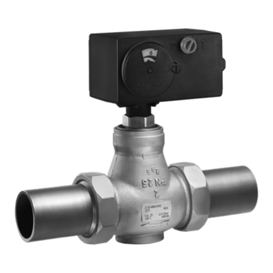
- Page 1 EB 5866 EN Translation of original instructions Type 3222/5857 Type 3222/5827 Type 3222/5825 Type 3222/5757-3 Type 3222/5757-7 Type 3222/2780-1 Type 3222/2780-2 with Type 3760 Positioner Type 3222/… Electric and Pneumatic Control Valves Edition April 2022...
- Page 2 Note on these mounting and operating instructions These mounting and operating instructions assist you in mounting and operating the device safely. The instructions are binding for handling SAMSON devices. The images shown in these instructions are for illustration purposes only. The actual product may vary.
-
Page 3: Table Of Contents
Contents Safety instructions and measures ..............1-1 Notes on possible severe personal injury ............1-5 Notes on possible personal injury ..............1-6 Notes on possible property damage .............1-8 Markings on the device ................2-1 Valve nameplate ..................2-1 Actuator nameplate ..................2-1 Design and principle of operation ...............3-1 Fail-safe action ...................3-1 Versions .....................3-3 Additional fittings ..................3-5... - Page 4 Decommissioning ..................10-1 Removal ....................11-1 11.1 Removing the valve from the pipeline ............11-1 11.2 Removing the actuator from the valve ............11-2 Repairs ....................12-1 12.1 Returning devices to SAMSON ..............12-1 Disposal ....................13-1 Certificates ....................14-1 Annex......................15-1 15.1 After-sales service ..................15-1 EB 5866 EN...
-
Page 5: Safety Instructions And Measures
SAMSON. SAMSON does not assume any liability for damage resulting from the failure to use the de- vice for its intended purpose or for damage caused by external forces or any other external factors. - Page 6 (see the 'Design and principle of operation' section). The fail-safe action of the actuator is the same as its direction of action and is specified on the nameplate of SAMSON actuators (see actuator documentation).
- Page 7 Start-up and shutdown procedures fall within the scope of the operator's duties and, as such, are not part of these mounting and operating instructions. SAMSON is unable to make any statements about these procedures since the operative details (e.g. differential pressures and temperatures) vary in each individual case and are only known to the operator.
- Page 8 Safety instructions and measures Referenced documentation The following documents apply in addition to these mounting and operating instructions: − Mounting and operating instructions for mounted actuator, e.g. SAMSON actuators: EB 5857 for Type 5857 u EB 5824-1/-2 for Type 5824 and Type 5825 EB 5827-1/-2 for Type 5827 u EB 5757-X for TROVIS 5757-X...
-
Page 9: Notes On Possible Severe Personal Injury
Safety instructions and measures 1.1 Notes on possible severe personal injury DANGER Risk of bursting in pressure equipment. Valves and pipelines are pressure equipment. Impermissible pressure or improper opening can lead to valve components bursting. Î Observe the maximum permissible pressure for valve and plant. Î... -
Page 10: Notes On Possible Personal Injury
Risk of personal injury due to preloaded springs. Pneumatic control valves (Type 3222/2780) using an actuator with preloaded springs are under tension. These control valves with SAMSON pneumatic actuators can be identified by the long bolts protruding from the bottom of the actuator. - Page 11 Safety instructions and measures WARNING Risk of personal injury due to exhaust air being vented. While the valve is operating, the pneumatic control valve (Type 3222/2780) vents during closed-loop control or when the valve opens or closes. Î Install the control valve in such a way that vent openings are not located at eye level and the actuator does not vent at eye level in the work position.
-
Page 12: Notes On Possible Property Damage
Safety instructions and measures WARNING Risk of personal injury through incorrect operation, use or installation as a result of information on the valve being illegible. Over time, markings, labels and nameplates on the valve may become covered with dirt or become illegible in some other way. As a result, hazards may go unnoticed and the necessary instructions not followed. -
Page 13: Markings On The Device
Markings on the device 2 Markings on the device 2.1 Valve nameplate SAMSON Δp Type designation Configuration ID Date of manufacture Model number Max. permissible temperature coefficient Max. perm. differential pressure The nameplate (48) is affixed to the valve body (see Fig. 2-1). - Page 14 EB 5866 EN...
-
Page 15: Design And Principle Of Operation
TÜV according to DIN EN 14597 in tor stem retracts. The plug is moved by combination with the SAMSON Type 3222 changing the control signal applied to the Valve. The registration number is available actuator. The valve and actuator have a on request. - Page 16 Design and principle of operation Fig. 3-1: Type 3222/2780-1 Fig. 3-3: Type 3222/5827, Type 3222/5724-3 · Version for water above 150 °C and steam Plug Connecting piece Body 11 Guide nipple Seat 14 Insulating section Fig. 3-2: Type 3222/5857, Type 3222/5757- O-ring 15 Insulating pipe 3, Type 3222/5757-7 EB 5866 EN...
-
Page 17: Versions
Design and principle of operation 3.2 Versions able for fail-safe action "Actuator stem ex- tends (FA)" or "Actuator stem retracts (FE)". Electric actuators The electric actuators can be controlled either using a three-step signal or, in the version with positioner, with continuous signals adjustable in the range from 0 to 20 mA or from 0 to 10 V. - Page 18 Design and principle of operation Table 3-1: Available versions and possible combinations (valve/actuator) Fail-safe action: Actuator stem Valve size DN Thread size G Type/ TROVIS Extends Retracts ½ ¾ Electric actuators 5857 – – • • • – • • •...
-
Page 19: Additional Fittings
Intermediate insulating piece An intermediate insulating piece (1990- Strainers 1712) must be used under the following con- We recommend installing a SAMSON ditions: Type 2 NI Strainer upstream of the valve. It − For medium temperatures from –15 °C prevents solid particles in the process medi- (red brass) or –10 °C (EN-GJS-400-18-... -
Page 20: Technical Data
Design and principle of operation 3.4 Technical data The nameplates on the valve and actuator provide information on the control valve version. See the 'Markings on the device' section and the associated actuator documentation. Table 3-2: Technical data for Type 3222 Valve size Globe valve with male thread connection or with flanged body... - Page 21 EPDM/FKM · Oil-resistant version: FKM Welding ends 1.0460 Threaded ends CW617N Screwed-on flanges 1.0460/1.0038 Noise emissions SAMSON is unable to make general statements about noise emissions. The noise emissions depend on the valve version, plant facilities and process medium. EB 5866 EN...
- Page 22 Design and principle of operation Dimensions and weights Table 3-5 provides a summary of the dimensions and weights of the valve. The lengths and heights in the dimensional drawings are shown on page 3-9 onwards. Table 3-5: Dimensions and weights for Type 3222 Valve Valves with male thread connection Valve size Length L...
- Page 23 Design and principle of operation Valves with female thread Connection size ½ ¾ – Width across flats SW – Length L – Female thread ½ ¾ – Weight without actuator – Version for water above 150 °C and steam or version with –...
- Page 24 Design and principle of operation Dimension diagrams for electric control valves (1) ≥25 146 x 103* 114 x 70 ≥25 Ø12 Type 3222/5857: DN 15 to 25 Type 3222/5824: DN 15 to 50 Type 3222/5757-3: DN 15 to 25 Type 3222/5825: DN 15 to 50 Type 3222/5757-7: DN 15 to 25 Type 3222/5724-3: DN 15 to 50 Type 3222/5724-8: DN 15 to 50 Type 3222/5725-3: DN 15 to 50...
- Page 25 Design and principle of operation Dimension diagrams for electric control valves (2) ≥25 154 x 107* Type 3222/5827: DN 15 to 50 * Dimensions for actuators with double stroking speed: 154x140 ≥25 154 x 107* Version for water above 150 °C and steam Type 3222/5827: DN 15 to 50 * Dimensions for actuators with double stroking speed: 154x140...
- Page 26 Design and principle of operation Dimension diagrams for pneumatic control valves ≥110 Ø168 ≥110 Ø168 Type 3222/2780-1: DN 15 to 50 Type 3222/2780-2: DN 15 to 50 Table 3-6: Weights of electric actuators Type 5857 5824 5825 5827-N 5827-A/-E Weight kg (approx.) 0.75 0.75 Table 3-7: Weights of electric actuators with process controller TROVIS ...
-
Page 27: Shipment And On-Site Transport
2. Check the shipment for transportation − Observe the permissible transportation damage. Report any damage to temperature of –20 to +65 °C. SAMSON and the forwarding agent (refer to delivery note). Note Contact our after-sales service for the trans- 4.2 Removing the packaging... -
Page 28: Storing The Valve
Î Observe the storage instructions. Î Avoid long storage times. − We recommend a storage temperature of Î Contact SAMSON in case of different 15 °C (59 °F) for elastomers. storage conditions or long storage peri- − Store elastomers away from lubricants, ods. -
Page 29: Installation
− Version for water above 150 °C and easily access the device from the work posi- steam tion. Î Contact SAMSON if the mounting posi- Pipeline routing tion is not as specified above. To ensure that the valve functions properly, proceed as follows: Î... -
Page 30: Preparation For Installation
Installation 5.2 Preparation for installation Support or suspension Before installation, make sure the following Note conditions are met: The plant engineering company is responsi- − The valve is clean. ble for selecting and implementing a suitable support or suspension of the installed control −... -
Page 31: Mounting The Device
Installation Proceed as follows: We recommend first installing the valve into the pipeline and mounting the actuator after- Î Lay out the necessary material and tools wards. to have them ready during installation work. Procedure to insulate cold systems Î Flush the pipelines. To insulate cold systems, we recommend to proceed as follows: Note... -
Page 32: Installing The Valve Into The Pipeline
This also applies to any required heat treatment Depending on the version, SAMSON control to be performed on the valve. valves are either delivered with the actuator Î Only allow qualified welding personnel already mounted on the valve or the valve to carry out welding operations. -
Page 33: Connecting The Actuator
Installation – TROVIS 5725-3 Electric Actuator Note with Process Controller u EB 5724 For electric control valves with positioner, an – TROVIS 5725-8 Electric Actuator initialization needs to be performed after the with Process Controller u EB 5724-8 initial start-up (see associated documenta- – TROVIS 5757-7 Electric Actuator tion). -
Page 34: Leak Test
Installation Î Wear hearing protection when working WARNING near the valve. Risk of personal injury due to preloaded springs (Type 3222/2780 Pneumatic Control Valve). WARNING WARNING Actuators with preloaded springs are under Crush hazard arising from actuator and tension. They can be identified by the long plug stem moving (Type 3222/2780 bolts protruding from the bottom of the actu- Pneumatic Control Valve). -
Page 35: Travel Motion
Installation 3. Depressurize the pipeline section and valve. Our after-sales service can support you to 4. Rework any parts that leak and repeat plan and perform a pressure test for your the leak test. plant. 5.4.2 Travel motion During the pressure test, make sure the fol- lowing conditions are met: The movement of the actuator stem must be linear and smooth. - Page 36 EB 5866 EN...
-
Page 37: Start-Up
Start-up 6 Start-up WARNING WARNING The work described in this section is only to Crush hazard arising from actuator and be performed by personnel appropriately plug stem moving (Type 3222/2780 qualified to carry out such tasks. Pneumatic Control Valve). Î Do not insert hands or finger into the yoke while the air supply is connected to WARNING the actuator. - Page 38 Start-up Before start-up or putting the valve back into service, make sure the following conditions are met: − The valve is properly installed into the pipeline (see the 'Installation' section). − The leak and function tests have been completed successfully (see the 'Testing the installed valve' section).
-
Page 39: Operation
Operation 7 Operation WARNING WARNING Immediately after completing start-up or put- Crush hazard arising from actuator and ting the valve back into operation, the valve plug stem moving (Type 3222/2780 is ready for use. Pneumatic Control Valve). Î Do not insert hands or finger into the yoke while the air supply is connected to WARNING the actuator. - Page 40 EB 5866 EN...
-
Page 41: Malfunctions
Malfunctions 8 Malfunctions Read hazard statements, warnings and caution notes in the 'Safety instructions and mea- sures' section. 8.1 Troubleshooting Malfunction Possible reasons Recommended action Actuator and plug stem Actuator is blocked. Check attachment. does not move on de- Remove the blockage. mand. -
Page 42: Emergency Action
Malfunctions Malfunction Possible reasons Recommended action Increased flow through Dirt or other foreign Shut off the section of the pipeline and flush the closed valve (seat leak- particles deposited be- valve. age) tween the seat and plug. Valve trim is worn out. Contact our after-sales service. -
Page 43: Servicing
Î Only use power interruption devices that are protected against unintentional re- Note connection of the power supply. The control valve was checked by SAMSON Î The electric actuators are protected before it left the factory. against spray water (IP 54). Avoid jets of −... - Page 44 Servicing WARNING WARNING WARNING Risk of hearing loss or deafness due to loud Risk of personal injury due to exhaust air noise. being vented (Type 3222/2780 Pneumatic Noise emission (e.g. cavitation or flashing) Control Valve). may occur during operation caused by the While the valve is operating, air is vented process medium and the operating from the actuator, for example, during...
- Page 45 Servicing We recommend the following inspection and testing which can be performed while the pro- cess is running: Inspection and testing Action to be taken in the event of a negative result: Check the markings, labels and name- Immediately renew damaged, missing or incorrect name- plates on the valve for their readability plates or labels.
- Page 46 EB 5866 EN...
-
Page 47: Decommissioning
Decommissioning 10 Decommissioning WARNING The work described in this section is only to Risk of burn injuries due to hot components be performed by personnel appropriately and pipeline. qualified to carry out such tasks. Valve components and the pipeline may be- come very hot. - Page 48 Decommissioning Î Do not impede the movement of the actu- To decommission the control valve for disas- ator and plug stem by inserting objects sembly, proceed as follows: into the yoke. 1. Close the shut-off valves upstream and Î Before unblocking the actuator and plug downstream of the control valve to stop stem after they have become blocked the process medium from flowing...
-
Page 49: Removal
Removal 11 Removal WARNING WARNING The work described in this section is only to Risk of personal injury due to residual be performed by personnel appropriately process medium in the valve. qualified to carry out such tasks. While working on the valve, residual process medium can escape and, depending on its properties, may lead to personal injury, e.g. -
Page 50: Removing The Actuator From The Valve
Removal Version with welding ends: cut the pipe- line in front of the weld seam. 3. Remove the valve from the pipeline. 11.2 Removing the actuator from the valve See associated actuator documentation. 11-2 EB 5866 EN... -
Page 51: Repairs
Î Do not perform any repair work on your outside of your shipment so that the own. documents are clearly visible. Î Contact SAMSON's After-sales Service 4. Send the shipment to the address given for repair work. on the RMA. - Page 52 12-2 EB 5866 EN...
-
Page 53: Disposal
Disposal 13 Disposal Î Observe local, national and internation- al refuse regulations. Î Do not dispose of components, lubricants and hazardous substances together with your household waste. EB 5866 EN 13-1... - Page 54 13-2 EB 5866 EN...
-
Page 55: Certificates
Certificates 14 Certificates The declarations of conformity according Pressure Equipment Directive 2014/68/EU are included on the next pages: EB 5866 EN 14-1... - Page 56 14-2 EB 5866 EN...
- Page 57 EB 5866 EN 14-3...
- Page 58 14-4 EB 5866 EN...
-
Page 59: Annex
You can reach our after-sales service at aftersalesservice@samsongroup.com. Addresses of SAMSON AG and its subsid- iaries The addresses of SAMSON AG, its subsid- iaries, representatives and service facilities worldwide can be found on our website (www.samsongroup.com) or in all SAMSON product catalogs. - Page 60 15-2 EB 5866 EN...
- Page 64 EB 5866 EN SAMSON AKTIENGESELLSCHAFT Weismüllerstraße 3 · 60314 Frankfurt am Main, Germany Phone: +49 69 4009-0 · Fax: +49 69 4009-1507 samson@samsongroup.com · www.samsongroup.com...
Need help?
Do you have a question about the 3222 Series and is the answer not in the manual?
Questions and answers