
Related Manuals for Samson 3760


Summary of Contents for Samson 3760
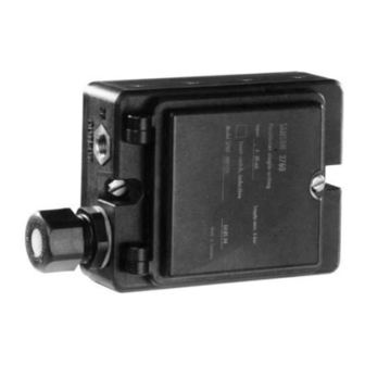
- Page 1 Pneumatic Positioner Electropneumatic Positioner Type 3760 Type 3760 Positioner Mounting and Operating Instructions EB 8385 EN Edition July 2012...
-
Page 2: Table Of Contents
Contents Contents Design and principle of operation....6 Attachment to actuators ......8 Adjusting the operating direction . - Page 3 Safety instructions The positioner is to be mounted, started up or operated only by trained and experienced personnel familiar with the product. According to these Mounting and Operating Instructions, trained personnel re- fers to individuals who are able to judge the work they are assigned to and recognize possible dangers due to their specialized training, their knowledge and experience as well as their knowledge of the applicable standards.
- Page 4 Versions Positioner Type 3760- Explosion protection Without II 2G Ex ia IIC T6 acc. to ATEX CSA/FM II 3G Ex nA II T6 acc. to ATEX Additional equipment Without Inductive proximity switches Pneumatic connections Electrical connections Without M20 x 1.5 blue M20 x 1.5 black...
- Page 5 Down to –40 °C with metal cable gland and Type 6112 i/p Converter Permissible ambient temperature Limits in test certificates additionally apply for explosion-protected devices. –40 to +70 °C for Type 3760-00x000 Pneumatic Positioner without inducti- ve limit switch Temperature: zero point: £ 0.03 %/°C · Span: £ 0.03 %/°C Influence Vibrations: between 5 and 120 Hz as well as 2 g £...
-
Page 6: Design And Principle Of Operation
(2). The positioner is designed for direct attach- ment to SAMSON Type 3277 Actuators. The control signal from the control unit, pro- vided it is a pneumatic signal, is applied di- rectly to the measuring diaphragm (3) as pressure signal p . - Page 7 Design and principle of operation Zero Travel Supply Booster direction of action >> 12 11 Span 1 Pressure regulator 2 i/p converter 3 Measuring spring 4 Diaphragm lever 5 Adjustment screw for zero 6 Lever Booster 7 Range spring direction of action <> 8 Adjustment screw for span 9 Clamping screw...
-
Page 8: Attachment To Actuators
Attachment to actuators Attachment to actuators In this case, the signal pressure must be routed from the signal pressure connection The positioner is attached directly to the ac- (output) to the actuator using a connecting plate. The switchover plate is no longer tuator yoke using the two screws inside the housing. -
Page 9: Connections
Attachment to actuators Switchover plate Hole for signal pressure Screw (parking position) Seal with filter Symbol Marking Actuator stem extends Actuator stem retracts Attachment: Left Right Left Right Direction of action: >> <> <> >> Fig. 3 · Signal pressure connection using a switchover plate for 120 cm² Vent plug Signal pressure connection with hook-up for with filter check valve for IP 65... - Page 10 Attachment to actuators The symbols indicating the direction of that the clamp is aligned at an exact action are marked on the booster. The de- right angle. sired symbol must be aligned with the arrow 3. Hook up the range spring between the stamped on the positioner housing.
- Page 11 Attachment to actuators Clamping screw Span adjuster Range spring Zero adjuster Span adjuster Fig. 4 · Mounting the clamp Range spring Color coding Reference Travel Order no. variable 0...100 % 12/15 Yellow 0...50 % 6/7.5 1400-6892 50...100 % 6/7.5 0...100 % 6/7.5 1400-6893 Green...
- Page 12 Attachment to actuators Accessories Order no. 120 cm² actuator 240 and 350 cm² actuators Mounting kit (clamp and cover plate) 1400-6898 1400-6899 Hook-up kit with 6 x 1 mm pipe for 240 and 350 cm² actuators Actuator stem extends Actuator stem retracts Actuator Left attachment Right attachment...
-
Page 13: Pneumatic Connections
Connections Connections nameplate; the direction of action is speci- fied by a symbol. Pneumatic connections Actuator stem extends: Fail-safe action "valve CLOSED" The pneumatic connections are designed as (with globe and angle valves) -18 NPT or ISO 228/1-G tapped holes. The supply input (SUPPLY 9) is fitted with a Required supply pressure = upper bench filter to clean impure air. -
Page 14: Electrical Connections
Connections Electrical connections Selecting cables and wires: Observe Clause 12 of EN 60079-14: 2008 For electrical installation, observe the (VDE 0165 Part 1) when installing intrinsi- relevant electrotechnical regulations cally safe circuits. The Subclause 12.2.2.7 and the accident prevention regula- applies when running multi-core cables con- tions that apply in the country of use. -
Page 15: Starting Point And Reference Variable
Operation – Adjustment Equipment for use in zone 2/zone 22 Operation – Adjustment In equipment operated with type of protec- Starting point and reference tion Ex nA II (non-sparking equipment) ac- variable cording to EN 60079-15: 2003, circuits may be connected, interrupted or switched The built-in range spring of the positioner is while energized only during installation, assigned to the rated valve travel and the in-... - Page 16 Operation – Adjustment Adjustment for actuator with The starting point (zero) in this case is 0.2 bar or 4 mA, the upper range value is 1 bar fail-safe action "Actuator or 20 mA. stem extends" In split-range operation, the controller output signal intended to actuate two control valves NOTICE is split into half to allow each valve to pass...
- Page 17 Operation – Adjustment Upper range value (travel) Adjustment for actuator with e.g. 1 bar (20 mA) fail-safe action "Actuator stem retracts" 3. After the starting point has been ad- justed, increase input signal. NOTICE The plug stem must stand still at an up- For actuator version "Actuator stem re- per range value of exactly 1 bar tracts", the diaphragm chamber must be...
- Page 18 Operation – Adjustment Upper range value (travel) NOTICE e.g. 0.2 bar (4 mA) After adjusting the positioner, close the actu- ator yoke with the cover plate. 5. After the starting point has been ad- Make sure that the vent plug in the cover justed, set the input signal to 0.2 bar plate is directed downwards when the con- (4 mA) at the remote adjuster (amme-...
-
Page 19: Adjusting The Limit Switch
Adjusting the limit switch The terminal used to connect the limit switch (41/42 or 51/52) can be written on the ad- The positioner version 3760-X1XXXX is hesive function label inside the positioner equipped with an inductive limit switch to cover. -
Page 20: Retrofitting A Limit Switch
Adjusting the limit switch Retrofitting a limit switch 2. Install support plate (8) on the aluminum plate adjacent to the terminal base using For installation of a limit switch in an i/p two screws. positioner (model index .02 and higher; 3. -
Page 21: Converting The Positioner
Converting the positioner Converting the positioner Remove plug (1) from the housing and replace it with a cable gland or plug The positioner can be converted from a connector. pneumatic to an electropneumatic positioner 3. Undo both mounting screws in the and vice versa using a conversion kit. - Page 22 Converting the positioner 7. Fasten i/p module in the housing using 3. Seal holes in the bottom of the housing the two screws. Make sure that the seal using the connecting plate (2) contain- (3) with the restriction is properly posi- ing the seal (3).
-
Page 23: Dimensions In Mm
Dimensions in mm Dimensions in mm M20 x 1.5 Pressure gauge for signal pressure OUTPUT Pneumatic connections Connector acc. to DIN 43650 EB 8385 EN... - Page 24 EB 8385 EN...
- Page 25 EB 8385 EN...
- Page 26 EB 8385 EN...
- Page 27 EB 8385 EN...
- Page 28 EB 8385 EN...
- Page 29 EB 8385 EN...
- Page 30 EB 8385 EN...
- Page 31 EB 8385 EN...
- Page 32 EB 8385 EN...
- Page 33 EB 8385 EN...
- Page 34 EB 8385 EN...
- Page 35 EB 8385 EN...
- Page 36 SAMSON AG · MESS- UND REGELTECHNIK Weismüllerstraße 3 · 60314 Frankfurt am Main · Germany Phone: +49 69 4009-0 · Fax: +49 69 4009-1507 EB 8385 EN Internet: http://www.samson.de...
Need help?
Do you have a question about the 3760 and is the answer not in the manual?
Questions and answers