Advertisement
Quick Links
Keithley Instruments
28775 Aurora Road
Cleveland, Ohio 44139
1-800-833-9200
tek.com/keithley
Overview
The Keithley Model 4210-MMPC-W multi-measurement prober cable kit provides a collection of matched
connection accessories. When properly installed, these accessories have the performance needed that allow
current-voltage (I-V), capacitance-voltage (C-V), and pulsed I-V parametric characterization measurements to be
made using a single prober cable setup. This kit is for use with a Wentworth prober.
This prober cable kit requires the Keithley Articulated Arm (Wentworth part number 2026-96509). Contact your
Wentworth representative to obtain the necessary manipulator arm and instructions.
This document contains information about the installation and use of this cable kit:
▪
Model 4200A-SCS instrument connections: Explains how to make connections from the 4200A-SCS to
the bulkhead.
▪
Prober bulkhead to prober pin connections (basic setup): Explains how to make connections from the
prober bulkhead to the prober pins.
▪
Usage scenarios: Provides the following specific prober cable setups:
▪
I-V testing (2-pin and 4-pin)
▪
C-V testing (2-pin and 4-pin)
▪
Pulsed I-V measurements using the Keithley Model 4225-PMU, and the 4225-PMU with the 4225-RPM
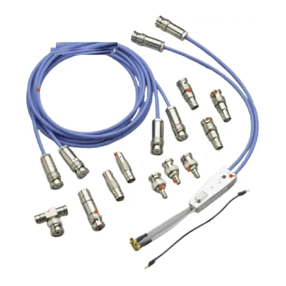
Prober cable kit contents
The following figure shows the cables, adapters, and supplies that are included in the Model 4210-MMPC-W
multi-measurement cable kit.
Each 4210-MMPC-W kit supplies the required components to make sense and force connections to
one pin. Additional kits are required to make additional connections.
PA-1085 Rev. B November 2023
Multi-measurement Prober Cable Kit
*PPA-1085B*
Model 4210-MMPC-W
1
Advertisement

Related Manuals for Tektronix KEITHLEY 4210-MMPC-W


Summary of Contents for Tektronix KEITHLEY 4210-MMPC-W
- Page 1 Model 4210-MMPC-W Keithley Instruments Multi-measurement Prober Cable Kit 28775 Aurora Road Cleveland, Ohio 44139 1-800-833-9200 tek.com/keithley Overview The Keithley Model 4210-MMPC-W multi-measurement prober cable kit provides a collection of matched connection accessories. When properly installed, these accessories have the performance needed that allow current-voltage (I-V), capacitance-voltage (C-V), and pulsed I-V parametric characterization measurements to be made using a single prober cable setup.
- Page 2 Model 4210-MMPC-W Multi-measurement Prober Cable Kit Figure 1: Model 4210-MMPC-W multi-measurement prober cable kit Item Description Keithley part number Prober cable assembly with clamp (blue), 37.5 cm CA-532 (14.75 in.) BNC jack to triaxial plug adapter CS-712 Triaxial to triaxial cable (blue), 61.0 cm (24 in.) CA-534-24 Triaxial jack to triaxial jack, high voltage adapter CS-751...
- Page 3 Model 4210-MMPC-W Multi-measurement Prober Cable Kit Model 4200A-SCS instrument connections To prevent injury or death due to electric shock, remove all power from the 4200A-SCS and shut down the Wentworth prober before installing the prober cable kit. Connect the Model 4200A-SCS instruments to the triaxial jacks on the prober bulkhead. See the following figure for an example.
- Page 4 Model 4210-MMPC-W Multi-measurement Prober Cable Kit I-V testing For I-V testing, connect the triaxial cables of the 4200A-SCS source-measure units (SMUs) to the standard triaxial jacks on the bulkhead. The following figure shows the prober connections for two SMUs. The 4200A-SCS to prober portion of the following figure shows SMUs that do not use preamplifiers. These SMUs use triaxial cables that are terminated with a miniature triaxial connector on one end and a standard triaxial connector on the other end.
- Page 5 Model 4210-MMPC-W Multi-measurement Prober Cable Kit C-V testing You need two prober cable kits to connect the subminiature version A (SMA) cables of the CVU to the triaxial jacks on the bulkhead of the prober. The following figure shows how to make the connections. Use the torque wrench supplied with the 4200A-SCS to tighten the SMA connections to 8 in.
- Page 6 Model 4210-MMPC-W Multi-measurement Prober Cable Kit Prober bulkhead to prober pin connections The following figure shows the basic cable setup for the 2-pin I-V and 2-pin C-V testing scenarios described in this document. The 4-pin I-V and 4-pin C-V testing scenarios require minor setup changes. Pulsed I-V setup, which is more complex, is described in Usage scenarios (on page 9).
- Page 7 Model 4210-MMPC-W Multi-measurement Prober Cable Kit Installation guidelines The following figure shows the prober cable assemblies of two 4210-MMPC-W kits installed in a Wentworth prober. To secure the cable assembly to the manipulator: 1. Secure each blue triaxial cable (2) to a manipulator using a single mounting screw (item 1 in the following figure).
- Page 8 Model 4210-MMPC-W Multi-measurement Prober Cable Kit 3. Route the blue cables along the sides of the manipulators as shown in the previous figure. When routing the wires, consider the possible movements of the manipulators and the movements of the camera or microscope. 4.
-
Page 9: Usage Scenarios
Model 4210-MMPC-W Multi-measurement Prober Cable Kit Usage scenarios The following usage scenarios provide information on how to set up 2-pin and 4-pin I-V tests, 2-pin and 4-pin C-V tests, and pulsed I-V tests. I-V testing: 2-pin I-V setup The setup for 2-pin I-V testing requires two prober cable kits. To perform 2-pin I-V testing, connect two 4200-SMUs or 4210-SMUs to the prober bulkhead and then use the setup shown in the following figure as a guide to connect to the device under test (DUT). - Page 10 Model 4210-MMPC-W Multi-measurement Prober Cable Kit I-V testing: 4-pin I-V setup The setup for 4-pin I-V testing requires four prober cable kits. With four SMUs connected to the prober bulkhead, use the setup shown in the following graphic to perform 4-pin I V testing.
- Page 11 Model 4210-MMPC-W Multi-measurement Prober Cable Kit C-V testing: 2-pin C-V setup The setup for 2-pin C-V testing requires two prober cable kits. With a CVU connected to the prober bulkhead, use the fundamental setup shown in C-V testing (on page 5) to perform 2-pin C-V testing.
- Page 12 Model 4210-MMPC-W Multi-measurement Prober Cable Kit C-V testing: 4-pin C-V setup The setup for 4-pin C-V testing requires four prober cable kits. A typical test for a field effect transistor (FET) is to connect the drain, bulk, and source together and make the measurement across the gate.
- Page 13 Model 4210-MMPC-W Multi-measurement Prober Cable Kit Set up the Keithley Model 4225-PMU for pulsed I-V measurements The setup for four-pin pulsed I-V testing requires four prober cable kits. The Model 4225-PMU is an Ultra Fast I-V Module that is an instrument card for the 4200A-SCS. The PMU has two channels of voltage pulsed source with integrated simultaneous voltage and current measurements.
- Page 14 Model 4210-MMPC-W Multi-measurement Prober Cable Kit Setup using the Keithley Model 4225-RPM for I-V, C-V, or pulsed I-V measurements The setup for three-pin pulsed I-V testing requires three prober cable kits. The setups for four-pin testing require four prober cable kits. The Model 4225-RPM Remote Amplifier/Switch is an optional accessory for the Model 4225-PMU.
- Page 15 Model 4210-MMPC-W Multi-measurement Prober Cable Kit Figure 15: Test setup for three-pin device using two-channel I-V and pulsed I-V Item Description Part number Notes Prober cable assembly CA-532 Triaxial jack to triaxial jack adapter CS-751 Ground jumper cable assembly (1 CA-535-7 The two jumpers connect the commons of the of 2)
- Page 16 Model 4210-MMPC-W Multi-measurement Prober Cable Kit Figure 16: Test setup for four-pin device using two-channel I-V and pulsed I-V Item Description Part number Notes Prober cable assembly CA-532 The three jumpers connect the commons of the Ground jumper cable assembly CA-535-7 four cable assemblies.
- Page 17 Model 4210-MMPC-W Multi-measurement Prober Cable Kit 4-terminal C-V test setup This four-pin setup requires four 4210-MMPC-W kits. For the C-V test setup shown in below, all four source/measure channels are used. Figure 17: Test setup for four-terminal C-V testing Item Description Part number Quantity...
-
Page 18: Safety Precautions
Safety precautions The following safety precautions should be observed before using this product and any associated instrumentation. Although some instruments and accessories would normally be used with nonhazardous voltages, there are situations where hazardous conditions may be present. This product is intended for use by personnel who recognize shock hazards and are familiar with the safety precautions required to avoid possible injury. - Page 19 For safety, instruments and accessories must be used in accordance with the operating instructions. If the instruments or accessories are used in a manner not specified in the operating instructions, the protection provided by the equipment may be impaired. Do not exceed the maximum signal levels of the instruments and accessories. Maximum signal levels are defined in the specifications and operating information and shown on the instrument panels, test fixture panels, and switching cards.
Need help?
Do you have a question about the KEITHLEY 4210-MMPC-W and is the answer not in the manual?
Questions and answers