
Subscribe to Our Youtube Channel
Related Manuals for Cembre PCM-2P


Summary of Contents for Cembre PCM-2P
- Page 1 MACHINE FOR PANDROL MACHINE FOR PANDROL “E-CLIP” FASTENING “E-CLIP” FASTENING PCM-2P OPERATION AND MAINTENANCE MANUAL ENGLISH ENGLISH (Translation of the original instructions)
- Page 2 - Machine operation is guaranteed only if used by well-trained users and expert on the adjustments on the machine itself. - The design or configuration of the machine shall not be modified other than by CEMBRE. - Cannot be used over switches and crossings.
-
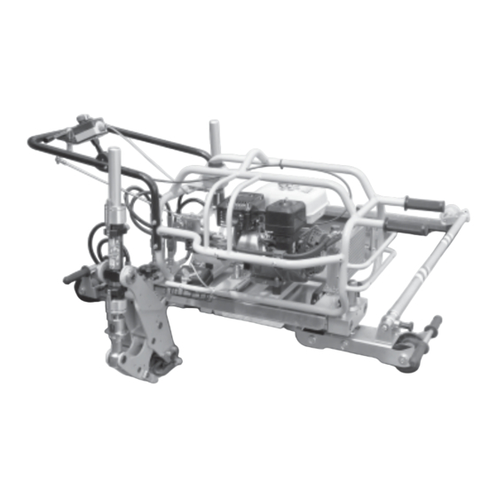
Page 3: General Characteristics
1. GENERAL CHARACTERISTICS – Application range: suitable for the insertion and extraction of Pandrol E-clip* used with 75 mm bases on standard-gauge rails (1435 mm). – Developed force (single clamp) ....................29.000 N – Resistance between rail and wheel: ....................≥1 MΩ –... -
Page 4: Machine Description
2. MACHINE DESCRIPTION (Ref. to Fig. 1) 01 – TRANSPORT HANDLES 02 – LIFTING POINT IN NEUTRAL POSITION 03 – HYDRAULIC PUMP OIL TANK 04 – ACCELERATOR 05 – WORKLIGHT ON/OFF SWITCH 06 – STOP/EMERGENCY BUTTON 07 – CLAMP CONTROL LEVER 08 –... - Page 5 PUMP UNIT CLAMP UNIT WHEEL BAR CARRIAGE FIG. 1 - MACHINE DESCRIPTION...
-
Page 6: Unpacking The Machine
3. UNPACKING THE MACHINE (Ref. to Fig. 1) To reduce overall dimensions and weight during transport, the machine is supplied disassem- bled as four units. It consists of four main sections which can be easily assembled/disassembled (Ref. Fig. 1): – Pump unit: combustion engine/hydraulic pump for clamp operation. - Page 7 WHEEL BAR CARRIAGE PUMP UNIT FIG. 2 – TRANSPORTING THE UNITS 4. INSTRUCTIONS FOR USE (Ref. to Fig. 4) 4.1) Assembly/disassembly of the machine Select the rail to be worked on and the direction of operation, then assemble the machine as follows, referring to Fig.
- Page 8 – Pull and turn the knob (41), insert the 3 wheel bar in the carriage housing as far as the stop, aligning the hole in the end of the rod with the pin knob. Release the knob (41) and the wheel (38) which will act as a support on the opposite rail so the assembly is stable and able to slide along the rail;...
- Page 10 4.1.2) Disassembly of the machine (Ref. to Fig. 4 and 4a) To disassemble the machine: – First lower the rear part and lock with pin (27), block wheel (30) then reverse the process de- scribed in § 4.1. – Before disconnecting the pump unit, make sure to have disconnected the hydraulic circuit and the braking device;...
- Page 11 4.3) Controls (Ref. to Fig. 5) After gripping the handlebar (08), the operator can easily access all the unit controls and, more specifically: – Accelerator control lever (04): changes engine rpm. – Worklight ON/OFF switch (05): in case of night work or bad lighting, the clamping area can be illuminated by these side mounted lamps.
- Page 12 4.4) Setting the machine (Ref. to Fig. 6) Before use, always check the height of the clamps with respect to the E clips. Taking a retention plate as a reference point, check the position of the clamps with respect to the plate itself.
- Page 13 4.4.2) Adjusting the height of the front of the machine (Ref. to Fig. 8) After making the adjustments described in § 4.4.1 proceed to adjust the machine horizontally as follows: FIG. 8 – Line up the side of the machine so that the clamp unit is parallel with the upper surface of the railhead.
- Page 14 4.5) Operation Before use, always check: – Integrity of the machine. – The correct coupling of the units making up the machine. – Correct connection of the quick couplings and the braking device. – Correct level of oil in pump. –...
- Page 15 – Pull the control lever to the right in "INSERT" position to gradually move the teeth for- wards with consequent insertion of both E clips (see Fig. 11b and 11c). When performing the insertion operation, each clamp teeth (33) will move in opposite directions.
- Page 16 4.5.2) Simultaneous extraction of 2 E clips (Ref. to Fig.12) Make sure the locking knob (27) of the wheel is released (see § 4.2). – Make sure the teeth (33) of the clamps are moved fully forwarded by pulling the control lever to the right in "INSERT"...
- Page 17 – After removal, pull the control lever to "INSERT" position for forward movement of teeth (33) (see fig. 12d). FIG. 12d NOTE: movement of one of the clamps is schematically shown in the illustrations; the other will have an identical and opposite movement.
-
Page 18: Starting The Engine
5. STARTING THE ENGINE – Move the stop button (06) (see § 4.3) to "ON" posi- FIG. 13a tion (see Fig. 13a). The engine will not start unless the red button (06) is lifted. – Move the fuel cock to "ON" position (see Fig. 13b). –... - Page 19 – Fit the plug back in the cap. – Move button (06) to ON. – After earthing the side electrode, pull the starting cable and check to see whether the plug produces a spark. If the engine still fails to start, contact CEMBRE (see § 7).
-
Page 20: Maintenance
All electrical and mechanical maintenance shall only be carried out by authorised persons in accordance with a safe system of work and CEMBRE instructions. Before servicing or removing any parts of the machine, stop the engine and allow it to cool. - Page 21 Before every use: – Check wheel for resistance, wheel should not be free rotating. – Ensure wheel is clean, removing any dirt or mud. – Check for signs of damage. Every 6 months: – Check for excessive braking on wheel. Wheel should roll along track when pushed, wheel will slide if excessive braking occurs.
- Page 22 6.1.2) Topping up the oil in the hydraulic pump (Ref. to Fig. 14a) Periodically check the level of the oil in the hydraulic pump. The oil should always be visible inside the tank (03). If the level is low, top up with the specific oil recommended: –...
- Page 23 6.1.4) Changing the gas springs (Ref. to Fig. 15) Replace the gas springs when required as follows: – Release the wheel arm so the springs are ex- tended position. – Using a flat-blade screwdriver, lift the retention collar at the end of the spring, pulling with force at the same time to release the spring from its gas spring screwdriver...
-
Page 25: Return To Cembre For Overhaul
Centre; if possible, attach a copy of the Test Certificate supplied by CEMBRE together with the machine or fill in and attach the form available in the “ASSISTANCE” section of the CEMBRE website. 8. OPTIONAL ACCESSORIES - MPC6 PRESSURE GAUGE code 2595209 To check maximum pressure valve setting. - Page 26 xxxxxx...
- Page 27 DECLARATION DE CONFORMITE - KONFORMITÄTSERKLÄRUNG - DECLARACIÓN DE CONFORMIDAD - DICHIARAZIONE DI CONFORMITÁ We Nous Wir Nos Noi: CEMBRE S.p.A. Via Serenissima, 9 – 25135 Brescia (Italy) Declare under our sole responsibility that the product - Déclarons sous notre seule responsabilité que le produit - Erklären in alleiniger Verantwortung dass das Produkt - Declaramos bajo nuestr responsabilidad que el producto...
- Page 28 CEMBRE S.p.A. CEMBRE Ltd. CEMBRE S.a.r.l. CEMBRE España S.L.U. CEMBRE GmbH CEMBRE GmbH CEMBRE Inc. 22 Avenue Ferdinand via Serenissima, 9 Dunton Park, Calle Verano 6 y 8 Geschäftsbereich Geschäftsbereich Raritan Center Business Park de Lesseps 25135 Brescia Kingsbury Road,...
Need help?
Do you have a question about the PCM-2P and is the answer not in the manual?
Questions and answers