Table of Contents
Advertisement
Quick Links
Advertisement
Table of Contents

Related Manuals for DKN SMART POWER MACHINE


Summary of Contents for DKN SMART POWER MACHINE
- Page 1 SMART POWER MACHINE OWNER’S MANUAL OWNER’S MANUAL WEBSITE...
- Page 3 Content -------------------------- ------------------------- -------------------------- -------------------------------- ------ ---------------------------- ----- ------------ -------...
-
Page 4: Chapter 1.Safety Instructions
Chapter 1.Safety Instructions Please read the safety information carefully before use the machine. 1. Safety warning Electrical current from power, telephone, and communication cables is dangerous . To avoid the risk of electric shock: plug or unplug cables , nor install, maintain , or reconfigure this product during a thunderstorm . - Page 5 2. Matters needing attention 1. When replacing the system battery, please use the same type of battery for replacement. 2. Some batteries contain lithium, which may explode if used, handled or handled improperly . To prevent accidents, do not: Throwing or immersing the battery in water ...
- Page 6 The owner’s manual is only for customers’ reference. ► The supplier cannot guarantee for mistakes occurring due to translation or change in technical specification of the product. ► DKN-Technology ASSUMES NO RESPONSIBILITY FOR PERSONAL INJURY OR PROPERTY DAMAGE SUSTAINED BY OR THROUGH THE USE OF THIS PRODUCT...
-
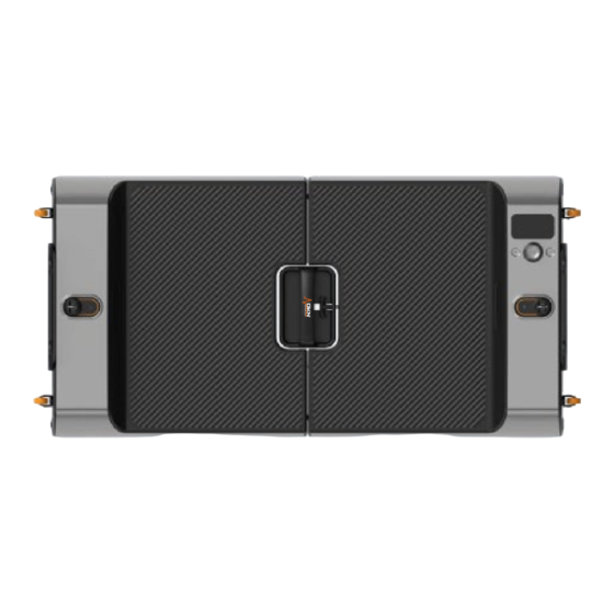
Page 7: Chapter 2.Product Appearance
Chapter 2.Product Appearance Front view back view... - Page 8 side view AC outlet and AC switch Disassembly back view...
-
Page 9: Chapter 3.Disassembly Guide
Chapter 3.Disassembly guide Explosion diagram of the whole machine(Send as attachment)... - Page 10 NAME NAME NAME Left Shield Upper Screen Bracket Cylinder Cover Short Edge Slow Drop Left Shaft Sleeve Foam Wheel Assembly Decorative Cover Long Edge Right Rack Motor Foam Assembly Axle Sleeve Soft 4.3 Inch Screen Roller Shaft Parts Screen Mount Roller Motor Mount Knob...
-
Page 11: Specification
Screw tightening torque reference table Torque Requirements (Except Thumb Screws and Nuts) Tightening torque Thread Specification (mm) (kgf.cm) M3x4 ~ M3x8 0.5-0.7 M4x8 ~ M4x12 0.7-1.0 7-10 1.2-1.5 12-15 Tools Used Screw berin Name Specification Pictures Cross recessed B head screw BM1.7 ×... - Page 12 Cross recessed B head screw ST4 × 8mm-nickel plated Cross recessed K head screw KM5×24mm-Black Nickel Plated KM6×12mm-Silver Nickel Cross recessed K head screw Plated-Fall Resistant M8 × 12mm-Black Nickel Hexagon head screw Plated-Fall Resistant TM4 × 10mm-Black Nickel Phillips T-head screw Plated PM4x8mm-With Outer Spline Cross recessed P head screw...
- Page 13 Hex nuts M8 × 8mm-nickel plated Phillips B head screw BM2 × 6mm-nickel plated Phillips B head screw BM2×8mm-nickel plated Phillips B head screw BM3 × 6mm-nickel plated BM4 × 16mm-Nickel Plated-Large Phillips B head screw Gasket...
-
Page 14: Material Specifications
Screw and Foam Location Information Sheet III. Serial Unit Number Total Material Specifications Location A Position B total arrive number dosage of parts amount Wireless Switch Wireless Switch ST1.4×4mm self-tapping screw -> Board Button ST1.7×4mm self-tapping screw Screen Mount -> Screen Bracket Right Shield STA2×6mm self-tapping screw... - Page 15 PFC Wide Voltage -> right rack M4×8mm countersunk Over-the-line -> folding board head (K head) screw plastic parts foot pad -> right rack M4×16mm machine screw foot pad -> left rack M4*16 machine tooth Spline shaft -> Motor shaft combination screw Motor &...
- Page 16 bracket Motor & Motor M8 gasket (Φ16×Φ8.5×2mm) Bull's Eye Wheel -> Control fixing bracket M10 flat pad (Φ18×Φ10.5×1.5mm) plug screw -> frame PWM3×6mm, with spacer screw, trumpet -> Speaker bracket spacer diameter 9mm PM4×5mm with external tooth Ground wire -> frame meson, ground screw...
- Page 17 Disassembly of structural parts 1. Take out the Long Rod Bracket, the Screw positions are as follows; Repair Instructions Before removing the Long Pole Bracket, it is recommended to lay the machine flat on the platform, and then use a screwdriver to unscrew the 4 screws shown in the figure.
-
Page 18: Repair Instructions
2. Take out the Swivel Wheels, the Screw Positions are as follows; Turn clockwise to tighten Turn counterclockwise to loosen Repair Instructions Directly align the plum blossom slot at the bottom of the swivel wheel with the Special Dismantling Tool for Swivel Wheel, and turn it counterclockwise to remove the 4 Swivel Wheels.(The Special Dismantling Tool is inside the bottom) Note that the tightening torque used must comply with the reference values for the specific type of screw. - Page 19 3. Take out the Bottom Shells of the left and right shields and the Upper Covers of the left and right shields. The screw positions are as follows; Repair Instructions Before removing the Bottom Cover of the left and right shields, it is recommended to lay the machine flat on a platform with a protective cushion, and then use a screwdriver to unscrew the screws shown in the figure.
- Page 20 The bottom cover of the right shield cannot be completely removed because the AC Socket and Power Cord are installed. You only need to lift the bottom cover of the right shield to 90 degrees to connect the 485 Communication Cable, Speaker Cable and Serial Port for upgrading to the display motherboard.
- Page 21 5. Take out the Speaker, the screw positions are as follows; Repair Instructions Use a screwdriver to remove the 4 screws shown in the figure. The picture above shows the location of the screws that secure the Speakers. After removing these screws, the Speakers on both sides can be removed.
- Page 22 6. Take out the speaker bracket, the screw positions are as follows; Repair Instructions Use a screwdriver to remove the screws as shown. The picture above shows the positions of the screws of the Speaker Brackets. Different colors represent different screw types.
- Page 23 7. Take out Motor Module and Electronic Control Module, the screw positions are as follows; Repair Instructions Use a wrench to unscrew the nylon nut as shown. The picture above shows the position of the screws of the Motor Module and Electronic Control Module. Different colors represent different screw types.
- Page 24 8. Take out the Motor Assembly, the screw positions are as follows; Repair Instructions Use a hex screwdriver to remove the screws as shown. The above picture shows the position of the screws of the Motor Assembly, and different colors represent different screw types.
- Page 25 9. Take out the lower cover of the Wire Rope Cover, and the screw positions are as follows; Repair Instructions Use a screwdriver to remove the screws as shown. The picture above shows the position of the screws of the Lower Cover Of the Wire Rope Cover, and different colors represent different types of screws.
- Page 26 10. Take out the Reel、the Reel Flange and the Reel Spool Spline Shaft, the screw positions are as follows; Repair Instructions Use a screwdriver to remove the screws as shown. The picture above shows the positions of the screws of the Reel Flange and the Reel Spline Shaft. Different colors represent different screw types.
- Page 27 11. Take out the Upper Cover Of The Wire Rope Cover, and the screw positions are as follows; Repair Instructions Use a screwdriver to remove the screws as shown. The picture above shows the position of the screws on the Upper Cover Of The Wire Rope Cover. Different colors represent different screw types.
- Page 28 12. Take out the Upper Cover Of The Wire Rope Cover, and the screw positions are as follows; Repair Instructions Use a screwdriver to remove the screws as shown. The picture above shows the position of the screws on the Upper Cover Of The Wire Rope Cover. Different colors represent different screw types.
- Page 29 Electronic parts removal 1. screw position Travel Switch Assembly Repair Instructions Use a screwdriver to remove the screws as shown. The figure above shows the location of the screws of the Travel Switch Assembly, after removing these screws, the Travel Switch Assembly can be removed. Note that the tightening torque used must comply with the reference values for the specific type of screw.
-
Page 30: Limit Switch
Limit switch Repair Instructions Use a screwdriver to remove the screws as shown. The figure above shows the location of the screws of the Travel Switch Assembly, after removing these screws, the Travel Switch can be removed. Note that the tightening torque used must comply with the reference values for the specific type of screw. - Page 31 Note that the tightening torque used must comply with the reference values for the specific type of screw. Otherwise the screws may be permanently damaged. R11 Display Motherboard Repair Instructions Use a screwdriver to remove the screws as shown. The figure above shows the position of the screws of the Display Board.
- Page 32 2. Maintenance guide ▓ Before replacing the Circuit Board, you need to remove the Rear Cover and Disconnect The Cables. Before replacing the Circuit Board, also cut off the power to prevent Short Circuit ▓ of the Wire Contacts. Be careful that the ports of the Cables are properly connected to prevent components from being burned by plugging into the wrong ports.
- Page 33 3D map of the whole machine Motor Power Module Special Filter Dismantling Tool Electronic Control PFC Wide Module Voltage Module Display Button (Left To Right) 1、Toggle Mode 2、Start/Stop&Knob 3、Toggle Left/Right...
- Page 34 Chapter 4.Internal cable...
- Page 35 Chapter 5.Electronic system block diagram...
-
Page 36: Chapter 6.List Of Key Parts
Chapter 6.List of key parts serial object number object description number U.S. Power Cord, U.S. Three-Plug-Suffix, UL/SJT/3×1.31mm²/OD8.5mm, 2000mm, 004.049.0052818 Black, Without PE Bag, BS 004.036.0054297 External AC power socket,3Pin,Black,DIP,with a set of rocker switches Ground wire, 4.8 in-line terminal TO fork terminal, 1015#16, 400mm, yellow-green, 004.049.0052821 without PE bag, GXD Overseas AC In-machine Power Cord, 4.8 Straight Plug End TO Fork Terminal... - Page 37 Chapter 7.Detailed description of all boards 一、Display Board Module 1. Display Motherboard: 1、 CN3 : Left and Right Speaker Sockets serial definition describe Defaults number ROUT+ Audio Right Channel Output + ROUT- Audio Right Channel Output - LOUT- Audio Left Channel Output - LOUT+ Audio Left Channel Output +...
- Page 38 2、 CN6 : 4.3 Inch LCD Screen Interface serial definition describe Defaults number G ND Ground VSYNC VSYNC HSYNC HSYNC RGB_DISP RGB_DISP PCLK PCLK G ND Ground LCD_B5 LCD_B LCD_B3 LCD_B2 LCD_B1 LCD_B0 LCD_G5 LCD_G4 LCD_G3 LCD_G2 LCD_G1 LCD_G0 LCD_R5 LCD_R4 LCD_R3...
- Page 39 LCD_R2 LCD_R1 LCD_R0 VCC-PANEL-3V3 VCC-PANEL-3V3 Ground LED+ LED+ LED- LED- 3 .485 Communication Interface +12V DC Power Supply G ND Ground RS485_A RS485_A RS485_B RS485_B G ND Ground 4.USB Burning Interface + 5V _ +5V DC Power Supply USB_DM _ USB_D - USB_DP _ USB_D+...
- Page 40 2. Motor Control Module 1.CN3 : AC socket serial definition describe Defaults number AC_L AC_N 2.CN2 : Motor Power Line Interface...
- Page 41 serial definition describe Defaults number 3 .CN6:485 Communication Interface +12V DC Power Supply G ND Ground RS485_B RS485_A RS485_A RS485_B G ND Ground 4.CN7: Encoder Interface ENC_Z- ENC_Z- ENC_Z+ ENC_Z+ ENC_B- ENC_B- ENC_B+ ENC_B+ ENC_A- ENC_A- ENC_A+ ENC_A+ ENC_5V ENC_5V ENC_GND ENC_GND...
-
Page 42: Chapter 8.Commissioning Instructions
Chapter 8.Commissioning instructions (factory menu、reset、 upgrade) 1. Software classification Power station software includes electronic control software and display control software 1、Electronic Control Software: Motor Control Program, use the RS485 Communication Line for programming and upgrading, and the pre-programming board needs to be programmed in advance to complete the Boothload software. (Boothload needs to be burned with an emulator, which is generally unnecessary) 2、Display and control software: display and interactive program software, use USB Communication Line to burn and upgrade... - Page 43 4. Wait for the home page to display the device connection successful message 5. Follow the steps of 1-2-3 to import the upgrade firmware, i.e. 6. After choosing to upgrade now, choose Yes...
- Page 44 7.After waiting for a while, you will be prompted twice whether to force the upgrade, choose yes for both 8.After the upgrade is successful, it will prompt that the programming is successful. Then you will be prompted to fill in the firmware failure (don't care about this, the upper computer software problem, just ignore it) 9.Wireless upgrade is in progress 10.
- Page 45 control software 1. Skip the intensification interface: as shown in the key definition above, press the mode key 3 times - "left and right switching keys press 3 times - "confirm key press 3 times ( the overseas version can skip this step) 2.
- Page 46 No.1: version check No.2: display check No.3: button check No.4: bluebooth check No.5: motor check Click the version, click the OK button to enter the version page, you can query the display control version number, SN code, and left and right motor version numbers, as shown in the following figure row:Motherboard version row:Mechine SN code...
- Page 47 Chapter 9.FAQ, Troubleshooting Checklist Fault Fault name Possible reason Recommended action code Restart the machine, if it still cannot be ALM_IPM_I Module damaged or 0x40 recovered, it is recommended to replace the NT_FO undervoltage Motor Control module Turn off the power and check whether the Module damaged or input power line and phase line are connected ALM_IPM_...
-
Page 48: Warranty
WARRANTY DKN-Technology warrants this product to be free from defects in material at the time of the product’s tender of delivery. This ‘Carry-in’ Limited Warranty applies for a period of two (2) years, beginning on the date mentioned on your product invoice or proof of purchase of product issue by DKN-Technology. - Page 49 WEBSITE Make an Appointment to Visit our Showroom...
Need help?
Do you have a question about the SMART POWER MACHINE and is the answer not in the manual?
Questions and answers