
Related Manuals for ensto Wallbox


Summary of Contents for ensto Wallbox
- Page 1 Ensto Wallbox Installation Instructions User Guide RAK111B_EN 2023-09-14 © 2023 Ensto Building Systems...
-
Page 2: Table Of Contents
Contents Installation Instructions 1. Safety instructions................................3 2. Description of symbols..............................3 3. Abbreviations................................... 4 4. Delivery contents................................4 5. Accessories..................................5 6. Mounting instructions..............................8 6.1. Before installation............................8 6.2. Wall mounting with wall bracket........................ 9 6.3. Ground mounting on concrete casting with ground mounting pole......... 10 6.4. -
Page 3: Installation Instructions
Installation Instructions 1. Safety instructions Electrically skilled person • The installation must only be done by a qualified professional. • Read these instructions carefully before you install, operate or maintenance the charging station. • Obey the instructions in this manual and make sure that the installation complies with national safety regulations, installation methods and restrictions. -
Page 4: Abbreviations
Label set with RCBO testing instructions (EVB100B-B4BC) • Triangular key • Installation Instructions / User Guide in English, other languages please see https://evwiki.ensto.technology/ Plastic front cover RFID reader 3-color LED indicates the charging point’s status Type label Painted steel frame Energy meter (EVB100B...) -
Page 5: Accessories
Flange KOT21715 Included in the delivery. Note! Cable glands are not included in the delivery. Please order suitable cable glands separately according to the used supply cable sizes, for example Ensto KTM... cable gland series (polyamide or brass). +0.1 -0.1 knock-outs EVTL40.00... - Page 6 EVTL43.00 Ground / Floor mounting pole The delivery includes flange F2202. Flange 2202 RAK111B_EN / 2023-09-14 6 / 32...
- Page 7 EVTL44.00 Adapter for ground mounting Ø54,5 Ø60,3 4 x M12 RAK111B_EN / 2023-09-14 7 / 32...
-
Page 8: Mounting Instructions
6. Mounting instructions 6.1. Before installation Remove the the charging station from its package. Do not scratch the surface of the the charging station after removal from the package. When selecting installation site, take into consideration the following: • The minimum space necessary for operating and maintenance. •... -
Page 9: Wall Mounting With Wall Bracket
6.2. Wall mounting with wall bracket Installation accessories Wall bracket EVTL40.00 1 pcs Screws 4 pcs Installation steps Remove the pre-installed wall bracket from the charging station [1]. Loosen the 2 fastening screws from the top of the charging station and 2 fastening screws from the bot- tom. -
Page 10: Ground Mounting On Concrete Casting With Ground Mounting Pole
6.3. Ground mounting on concrete casting with ground mounting pole Installation accessories Ground mounting pole EVTL43.00 1 pcs Anchor bolts M12 4 pcs Bolts and nuts (not included) Make sure that the materials used for the concrete casting and the installation procedures follow local building regulations and safety standards. -
Page 11: Ground Mounting On Concrete Foundation With Ground Mounting Pole
6.4. Ground mounting on concrete foundation with ground mounting pole Installation accessories Ground mounting pole EVTL43.00 1 pcs Adapter for concrete foundation EVTL44.00 1 pcs Concrete foundation (from different manufacturers) 1 pcs Bolts, washers and nuts (not included) Installation steps Dig a trench for cable conduits and an excavation pit for the concrete foundation to applicable depths. -
Page 12: Ground Mounting On Unimi Concrete Foundation
6.5. Ground mounting on Unimi concrete foundation This installation example describes the installation procedure when a concrete foundation supplied by Unimi - Solutions is used. Installation accessories Ground mounting pole EVTL43.00 1 pcs (1 x EVB) 2 pcs (2 x EVB) Installation accessories, Concrete foundation 1 pcs... - Page 13 Lift the foundation into the installation pit. You can use the attachment bar in the foundation as a lifting point. Make sure that the mounting bar is in a direction that enables the installation of the charging station in correct position. Put cable conduits into the trenches and install the conduits to relevant inlets.
-
Page 14: Attaching Charging Station To Mounting Pole Evtl43.00
6.6. Attaching charging station to mounting pole EVTL43.00 Installation steps Open the front cover lock and remove the front cover. Remove the flange at the bottom of the charging station frame. Use the multigate gland plate F2202 (included in the mounting pole delivery) to make sure that the ingress protection rating will be suf- ficient. -
Page 15: Electrical Connections
7. Electrical connections 7.1. Wiring instructions Open the front cover lock and remove the front cover. Remove the plastic shield. You can remove the steel bracket on the front, if it is necessary to get more space during the instal- lation work. -
Page 16: Power Supply
7.2. Power supply The voltage and current ratings including cables and line protector dimensioning must comply with na- tional regulations. System dimensioning must be done by a qualified electrical designer. Connect separate supply cables for each charging outlet. We recommend supply cables with stranded conductors. Supply connection to charging station with one outlet EVB100B-B4BC •... - Page 17 Supply connection to charging station with two outlets EVB200B-A4BC • A Residual current protection device (RCD type A, 30mA) and a circuit breaker (MCB max. 32A) for each charging outlet must be installed in the switchboard. Note! Phase rotation inside the charging station is not allowed. TN network L1 L2 L3 N PE L1 L2 L3 N PE Supply 1...
-
Page 18: Commissioning
Optocoupler input Control of charging event via ured on charging station settings. Please (+ / - 12V) external device / input ask your Ensto representative for details. EVB100... EVB200... control unit on the left side Ethernet 2 Ethernet 1 Micro SIM card holder... -
Page 19: Connecting To The Charging Station
EVB200... control unit on the right side Opto1- / Opto1+ Opto2- / Opto2+ Optocoupler input 12V Optocoupler input 12V USB B service port Ethernet 1 Ethernet 2 8.2. Connecting to the charging station If you want to change the default settings, you must connect to the charging station via web configura- tion tool to be able to start configure the commissioning settings. -
Page 20: Ethernet Connections
8.3. Ethernet connections Chaining the Ethernet connections is allowed. EVB200: Connect the Ethernet input to the ETH1 connector on the left side control unit. ETH 1 ETH 2 ETH 1 ETH 2 ETH 1 ETH 2 Charging station 1 Charging station 2 Charging station 3 8.4. -
Page 21: Technical Data
Take into consideration that the WiFi environment is by nature changing, so it can change dur- ing the life cycle of the charging system. Please see detailed commissioning instructions on https://evwiki.ensto.technology/ 9. Technical data EVB100B-A4BC Electrical connections... - Page 22 Design and mechanics Materials Frame: Powder coated mild steel Cover: Plastic (PETG and ABS) Color Frame: RAL7021 “Anthracite” Cover: White and black tape Sticker on the cover: Black Weight EVB100B-A4BC: approx. 11 kg EVB100B-B4BC: approx. 12 kg EVB200B-A4BC: approx. 13 kg Ingress protection rating IP54 Shock protection rate...
-
Page 23: Code Key
Cybersecurity • Ensto charging stations are designed to be safe to use according to relevant cybersecurity require- ments, where regular security penetration tests are done and all the known vulnerabilities are miti- gated. • The manufacturer provides regular firmware updates. The responsibility to update the charger firm- ware is under operator/owner/back-office provider. -
Page 24: Dimensional Drawing
11. Dimensional drawing EVB100B RAK111B_EN / 2023-09-14 24 / 32... - Page 25 EVB200B RAK111B_EN / 2023-09-14 25 / 32...
-
Page 26: Installation / Commissioning Checklist
12. Installation / Commissioning checklist Introduction Examine the mechanical and electrical installation in accordance with this checklist to make sure that the charging station is properly installed. Checking the Installation Examine the visual, mechanical and electrical installation when the charging station is un- powered. -
Page 27: Maintenance / Preventive Maintenance Instructions
13. Maintenance / Preventive maintenance instructions Recommended 1 x per year, take into consideration local regulations and national standards. Protect the charging station against pollution (water, snow, dust). WARNING Danger of electrical shock or injury! Risk of fire! Disconnect power before working inside the device or removing any components. MAINTENANCE ACTION Retighten all the screws on electric components. -
Page 28: Testing Instructions For The Electric Protective Device
14. Testing instructions for the electric protective device EVB100B-A4BC / EVB200B-A4BC Test the residual current device at the supply line. EVB100B-B4BC Press the TEST button. • The rocker turns to 0 position. • • Turn the rocker back to I position. •... -
Page 29: Warranty
16. Warranty Warranty conditions, see www.ensto.com/building-systems 17. Declaration of Conformity The EU declaration of conformity is available at the following internet address: https://evwiki.ensto.technology/display/CHWI/Certificates 18. Disposal Do not dispose of electrical and electronic devices including their accessories with the household waste. -
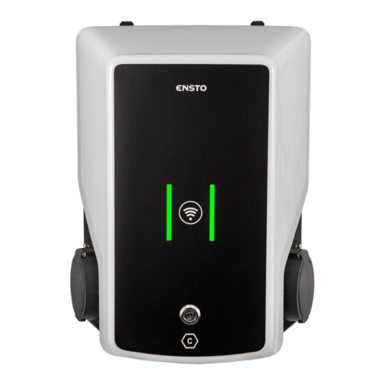
Page 30: User Guide
User Guide 19. User interfaces LED indicator lights will show the status of the charging point as described below: Charging point’s status LED light LED operation The charging point is free and ready to use Green Stable RFID read, authorization ongoing Green Flashing Charging authorization rejected... -
Page 31: Charging With Rfid
20.2. Charging with RFID You must have an RFID tag which has a permission to access the charging point. Start Charging with RFID Plug the charging cable to your electric vehicle. Plug the charging cable to the charging point. Show the RFID tag to the RFID reading area. While the RFID tag is read, the LED indicator flashes green and verifies the user permission to charge. - Page 32 Ensto Chago Oy Ensio Miettisen katu 2, P.O. Box 77 FIN-06101 Porvoo, Finland Tel. +358 204 76 21 www.ensto.com/building-systems...