
Subscribe to Our Youtube Channel
Related Manuals for ensto EVB200EB-B4BC


Summary of Contents for ensto EVB200EB-B4BC
- Page 1 EVB200EB-B4BC Installation Instructions User Guide RAK139_EN 2023-09-14 © 2023 Ensto Building Systems...
-
Page 2: Table Of Contents
Contents Installation Instructions 1. Safety instructions................................3 2. Description of symbols..............................3 3. Abbreviations................................... 4 4. Delivery contents................................4 4.1. Product features..............................4 4.2. Mounting accessories............................. 5 5. Accessories..................................6 6. Mounting instructions..............................8 6.1. Before installation............................8 6.2. Cable entries..............................9 6.3. -
Page 3: Installation Instructions
Installation Instructions 1. Safety instructions Electrically skilled person • The installation must only be done by a qualified professional. • Read these instructions carefully before you install, operate or maintenance the charging station. • Obey the instructions in this manual and make sure that the installation complies with national safety regulations, installation methods and restrictions. -
Page 4: Abbreviations
Mounting accessories • Label set with RCBO testing instructions • Triangular key • Installation Instructions / User Guide in English, other languages please see https://evwiki.ensto.technology/ 4.1. Product features Extension box Plastic front for electrical cover connections RCBO type A 30mA... -
Page 5: Mounting Accessories
4.2. Mounting accessories Item Description and use Quantity Screw 3x8, Tx10 • To lock the covers on the protective devices and the energy meters RJ45 connector • For Ethernet connections Cable gland M32 • For chaining power supply to another charging station Cable gland M16 •... -
Page 6: Accessories
5. Accessories EVTL43.00 Ground / Floor mounting pole Flange 2202 (not necessary with this product) RAK139_ENG / 2023-09-14 6 / 36... - Page 7 EVTL44.00 Adapter for ground mounting Ø54,5 Ø60,3 4 x M12 RAK139_ENG / 2023-09-14 7 / 36...
-
Page 8: Mounting Instructions
6. Mounting instructions 6.1. Before installation Remove the charger and the extension box from their package. Do not scratch the surface of the items after removal from the package. When selecting installation site, take into consideration the following: • The minimum space necessary for operating and maintenance. •... -
Page 9: Cable Entries
6.2. Cable entries • Take the cable routing into consideration when planning the installation. The supply cable can be routed into the enclosure from the top or bottom. Default cable routing is from the top. • An M32 cable gland for the supply cable and an M16 for a possible data cable are pre-assembled on the top of the extension box. -
Page 10: Wall Mounting
6.3. Wall mounting Installation accessories Screws max. Ø 6mm (not included) 4 pcs Installation steps Drill screw holes for the wall brackets. Select applicable screws for the the wall. Attach the extension box to the wall with 4 fastening screws. See wiring instructions on page 16. -
Page 11: Ground Mounting On Concrete Casting With Ground Mounting Pole
6.4. Ground mounting on concrete casting with ground mounting pole Installation accessories Ground mounting pole EVTL43.00 1 pcs Anchor bolts M12 4 pcs Bolts and nuts (not included) Make sure that the materials used for the concrete casting and the installation procedures follow local building regulations and safety standards. -
Page 12: Ground Mounting On Concrete Foundation With Ground Mounting Pole
6.5. Ground mounting on concrete foundation with ground mounting pole Installation accessories Ground mounting pole EVTL43.00 1 pcs Adapter for concrete foundation EVTL44.00 1 pcs Concrete foundation (from different manufacturers) 1 pcs Bolts, washers and nuts Installation steps Dig a trench for cable conduits and an excavation pit for the concrete foundation to applicable depths. -
Page 13: Ground Mounting On Unimi Concrete Foundation
6.6. Ground mounting on Unimi concrete foundation This installation example describes the installation procedure when a concrete foundation supplied by Unimi - Solutions is used. Installation accessories Ground mounting pole EVTL43.00 1 pcs (1 x EVB) 2 pcs (2 x EVB) Installation accessories, Concrete foundation 1 pcs... - Page 14 Lift the foundation into the installation pit. You can use the attachment bar in the foundation as a lifting point. Make sure that the mounting bar is in a direction that enables the installation of the charging station in correct position. Put cable conduits into the trenches and install the conduits to relevant inlets.
-
Page 15: Attaching Charging Station To Mounting Pole Evtl43.00
6.7. Attaching charging station to mounting pole EVTL43.00 Precondition • The mounting pole is mounted on site properly. • The cable glands are moved from top to the bottom of the extension box. See chapter 6.2 Cable entries. The electrical cables are installed and routed to the extension box. See chapter 7.1 Wiring instruc- •... -
Page 16: Electrical Connections
7. Electrical connections 7.1. Wiring instructions Installation steps Remove the front plate from the extension box. Remove the bolts, nuts and washers from the flange on the extension box. You need the bolts and washers when you attach the charger to the extension box. Remove the flange from the extension box. - Page 17 12. Lift the charger on the extension box. 13. Attach the charger to the extension box with the bolts and washers you removed in the step 2. 14. Remove the front cover from the charger. 15. Remove the plastic shield. RAK139_ENG / 2023-09-14 17 / 36...
- Page 18 Ethernet RJ45 connectors Connector for the Connector for the socket on the left socket on the right Bus connector for the energy meters 16. Connect the plug-in couplers from the charger to the respective couplers in the extension box. 17. Attach the plastic shield in place. 18.
-
Page 19: Power Supply
7.2. Power supply The voltage and current ratings must comply with national regulations. System dimensioning must be done by a qualified electrical designer. TN network Power Supply We recommend supply cables with Data cable stranded conductors. IN OUT Extension box RCBO RCBO Energy... - Page 20 IT network If you connect the charging station to an IT network, you must set the energy meter to 2-phase mode from the energy meter settings. Power Supply We recommend supply cables with Data cable stranded conductors. IN OUT Extension box RCBO RCBO Energy...
- Page 21 Parallel connection of charging stations The maximum quantity of connected charging stations depends on the system dimensioning made by qualified professional. Power Supply Data cable Supply cable Ø 18 - 25 mm (MCMK 4x25+16) ETH1 ETH2 ETH1 ETH2 Charging station 1 Charging station 2 Alternative cable entry from bottom See chapter 6.2.
-
Page 22: Commissioning
Optocoupler input Control of charging event via ured on charging station settings. Please (+ / - 12V) external device / input ask your Ensto representative for details. Control unit on the left side Ethernet 2 Ethernet 1 Micro SIM card holder... -
Page 23: Connecting To The Charging Station
8.2. Connecting to the charging station If you want to change the default settings, you must connect to the charging station via web configura- tion tool to be able to start configure the commissioning settings. Use Firefox, Chrome or Windows Edge web-browser for configuring. - Page 24 Take into consideration that the WiFi environment is by nature changing, so it can change dur- ing the life cycle of the charging system. Please see detailed commissioning instructions on https://evwiki.ensto.technology/ RAK139_ENG / 2023-09-14 24 / 36...
-
Page 25: Technical Data
9. Technical data Electrical connections Nominal supply voltage * 3-ph, 400 VAC Charging current (nominal) 3 x 32A Charging power (nominal) 2 x 22kW L1, L2, L3, N, PE Supply connections and Cu 2.5–50 mm² (according to supply current and local regulations) terminals Tightening torque: 4 Nm (2.5 - 4 mm²), 10 Nm (6 - 50 mm²) Grid connections... - Page 26 Cybersecurity • Ensto charging stations are designed to be safe to use according to relevant cybersecurity require- ments, where regular security penetration tests are done and all the known vulnerabilities are miti- gated. •...
-
Page 27: Code Key
Mode 3 lock release, RFID, LED, 6mA RCMB, OCPP1.6-JSON, RCBO Product generation B 1 x Mode 3/ Type 2 socket outlet 2 x Mode 3/ Type 2 socket outlets 200E 2 x Mode 3/ Type 2 socket outlets and extension box Ensto Wallbox RAK139_ENG / 2023-09-14 27 / 36... -
Page 28: Dimensional Drawing
11. Dimensional drawing RAK139_ENG / 2023-09-14 28 / 36... -
Page 29: Installation / Commissioning Checklist
12. Installation / Commissioning checklist Introduction Examine the mechanical and electrical installation in accordance with this checklist to make sure that the charging station is properly installed. Checking the Installation Examine the visual, mechanical and electrical installation when the charging station is un- powered. -
Page 30: Maintenance / Preventive Maintenance Instructions
13. Maintenance / Preventive maintenance instructions Recommended 1 x per year, take into consideration local regulations and national standards. Protect the charging station against pollution (water, snow dust). WARNING Danger of electrical shock or injury! Risk of fire! Disconnect power before working inside the device or removing any components. MAINTENANCE ACTION Retighten all the screws on electric components. -
Page 31: Testing Instructions For The Electric Protective Device (Rcbo)
14. Testing instructions for the electric protective device (RCBO) Press the TEST button. • The rocker turns to 0 position. • • Turn the rocker back to I position. • If a fault occurs, contact an electrician. 15. Troubleshooting Charging station is off, no lights on Issue Corrective action Mains voltage does not exist in the supply con-... -
Page 32: Warranty
16. Warranty Warranty conditions, see www.ensto.com/building-systems 17. Declaration of Conformity The EU declaration of conformity is available at the following internet address: https://evwiki.ensto.technology/display/CHWI/Certificates 18. Disposal Do not dispose of electrical and electronic devices including their accessories with the household waste. -
Page 33: User Guide
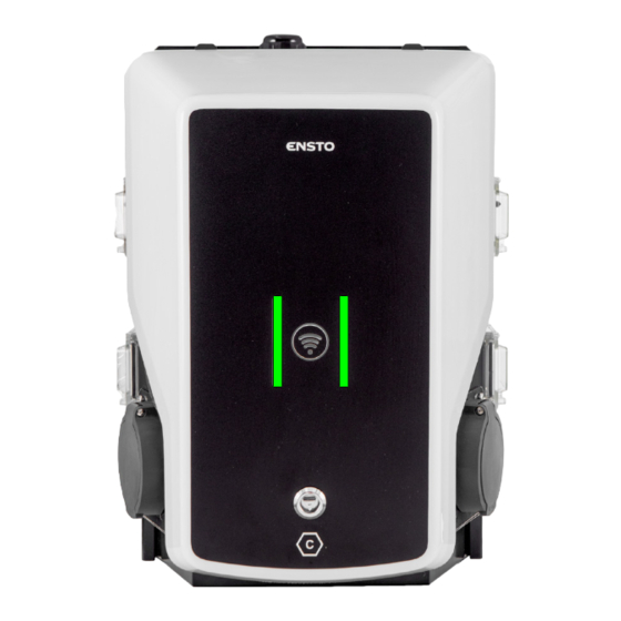
User Guide 19. User interfaces LED indicator lights will show the status of the charging point as described below: Charging point’s status LED light LED operation The charging point is free and ready to use Green Stable User identification Green Flashing User authorization is rejected / Charging is not allowed Flashing... -
Page 34: Charging With Rfid
20.2. Charging with RFID You must have an RFID tag which has a permission to access the charging point. Start Charging with RFID Plug the charging cable to your electric vehicle. Plug the charging cable to the charging point. Show the RFID tag to the RFID reading area. While the RFID tag is read, the LED indicator flashes green and verifies the user permission to charge. - Page 35 RAK139_ENG / 2023-09-14 35 / 36...
- Page 36 Ensto Chago Oy Ensio Miettisen katu 2, P.O. Box 77 FIN-06101 Porvoo, Finland Tel. +358 204 76 21 www.ensto.com/building-systems...
Need help?
Do you have a question about the EVB200EB-B4BC and is the answer not in the manual?
Questions and answers