
Related Manuals for ensto Pro EVF200


Summary of Contents for ensto Pro EVF200
- Page 1 Ensto Pro EVF200 / EVF300 Installation Instructions User Guide RAK112B_ENG 2023-06-27 © 2023 Ensto Building Systems...
-
Page 2: Table Of Contents
Contents Installation Instructions 1. Safety instructions..............................3 2. Description of symbols............................3 3. Abbreviations................................4 4. Delivery contents..............................4 5. Accessories - installation method and site..................... 5 6. Accessories - order numbers and dimensions....................6 7. Mounting instructions............................10 7.1. Before installation........................... 10 7.2. -
Page 3: Installation Instructions
Installation Instructions 1. Safety instructions Electrically skilled person • The installation must only be done by a qualified professional. • Read these instructions carefully before you install, operate or maintenance the charging station. • Obey the instructions in this manual and make sure that the installation complies with national safety regulations, installation methods and restrictions. -
Page 4: Abbreviations
• Triangular key • Installation Instructions / User Guide Ensto Pro (EVF) is a solution for charging two electric vehicles. It is engineered especially for fast AC charging. 3-color LED indicates the status of the charging point Mode 3 compatible... -
Page 5: Accessories - Installation Method And Site
5. Accessories - installation method and site The delivery does not include any installation accessories. Please order applicable accessories for the selected mounting method separately. EVF200 Installation method Accessories and site Ground mounting on Anchor bolts from a local supplier concrete at site Ground mounting on ground mounting... -
Page 6: Accessories - Order Numbers And Dimensions
EVF300 Installation method Accessories and site Ground mounting on Anchor bolts from a local supplier concrete at site Ground mounting on Concrete foundation, concrete foundation product code SJR-08 from Sähkö-Jokinen Oy, https://www.sahkojoki- nen.fi/en EVTL35.00: Ground mounting EVTL37.00: Adapter 6. Accessories - order numbers and dimensions EVTL32.00 ground mounting box for EVF200 EVTL32.00 is a ground mounting box with cable entry from bottom. - Page 7 EVTL34.00 ground mounting box for EVF200 EVTL34.00 is a ground mounting box with cable entry from top. Cable entry Cable route Cable glands M40x1.5 EVTL28.00 Ground mounting frame for EVF200 EVTL28.00 is a whole set as shown on the picture. RAK112B_ENG / 2023-06-27 7 / 40...
- Page 8 EVTL36.00 concrete foundation adapter for EVF200 The concrete foundation adapter is designed to be used with a concrete foundation, product code SJR-08, supplied by Sähkö-Jokinen Oy. Please order the foundation from: https://www.sahkojokinen.fi/en If you want to use a foundation from another manufacturer, make sure that the foundation is compatible with the adapter.
- Page 9 EVTL37.00 concrete foundation adapter for EVF300 The concrete foundation adapter is designed to be used with Sähkö-Jokinen SJR-08 foundation. Please order the foundation from: https://www.sahkojokinen.fi/en If you want to use a foundation from another manufacturer, make sure that the foundation is compatible with the adapter.
-
Page 10: Mounting Instructions
7. Mounting instructions 7.1. Before installation Remove the package around the charging station. Remove the film protecting the metal parts only after the installation is completed. Note! When you select the installation location, take into consideration the minimum space necessary for operating and maintenance. -
Page 11: Evf200 Mounting On Concrete Casting At Site
7.2. EVF200 mounting on concrete casting at site Installation accessories Ground mounting box EVTL32.00 / EVTL34.00 1 pcs Anchor bolts M12 4 pcs Washers Nuts Make sure that the materials used for the concrete foundation and the installation procedures follow local building regulations and safety standards. - Page 12 Put the anchor bolts in place and tighten the anchor bolt nuts. Adjust the upper nuts and washers on the anchor bolts horizontally. Use a spirit level. Attach the mounting box to the anchor bolts with applicable washers and nuts. Ground mounting box EVTL32.00 EVTL32.00: Pull electrical cables through the ground mounting box cable gland(s) approx.
-
Page 13: Evf200 Mounting On Ground Mounting Frame
7.3. EVF200 mounting on ground mounting frame Installation accessories Ground mounting frame EVTL28.00 1 pcs Ground mounting box EVTL32.00 / EVTL34.00 1 pcs Make sure that the materials used for the concrete foundation and the installation procedures follow local building regulations and safety standards. •... -
Page 14: Evf200 Mounting On Concrete Foundation
M12 Threaded bar Ground mounting box EVTL32.00 or EVTL34.00 Ground surface Ground mounting frame EVTL28.00 Concrete Cable protection pipe ~500 7.4. EVF200 mounting on concrete foundation Installation accessories Ground mounting box EVTL32.00 / EVTL34.00 1 pcs Adapter for concrete foundation EVTL36.00 1 pcs Concrete foundation 1 pcs... - Page 15 Installation steps Assemble the concrete foundation adapter. Attach the mounting box EVTL32.00 / EVTL34.00 on the concrete foundation adapter EVTL36.00 and put the assembly on the concrete foundation. Attach the assembly in place. Use the screws on the concrete foundation. EVTL32.00: Pull electrical cables through the ground mounting box cable gland(s) approx.
-
Page 16: Evf200 Mounting On Unimi Concrete Foundation
Please order the following items from www.unimi.se Concrete foundation Ensto Pro, product code 100-1 1 pcs Cover plate 1 pcs Ensto EVF compatible adapter element, product code 100-13 1 pcs Installation steps Figure 1 • Dig a trench for cable conduits and an excavation pit for the concrete foundation to applicable depths. - Page 17 Figure 4 • Put the adapter element on the foundation. • Attach the adapter element to the foundation attachment bar with bolts 3 pcs (included). • Remove the upper nuts and upper pair of washers from the adapter element. (Make sure that there is one polyamide washer on each side of the mounting box.) •...
-
Page 18: Evf300 Mounting On Concrete Casting At Site
7.6. EVF300 mounting on concrete casting at site Installation accessories Ground mounting box EVTL35.00 1 pcs Anchor bolts M12 8 pcs Washers Nuts Make sure that the materials used for the concrete foundation and the installation procedures follow local building regulations and safety standards. •... - Page 19 Adjust to the same level Washer upper surface measured from ground Anchor bolt Concrete Select anchor bolts applicable for the thickness and strength of the concrete Attach the mounting box to the anchor bolts with applicable washers and nuts. Pull electrical cables through the ground mounting box cable gland(s) approx. 450 mm measured from the upper surface of the mounting box.
- Page 20 Remove the nuts and the washers from the ground mounting box. Open the maintenance door of the distribution cabinet. Lift the distribution cabinet module on the mounting box and attach it in place, max. tightening torque 14 Nm. 10. Remove the supply cable sheath at the length of max. 200 mm. 11.
-
Page 21: Evf300 Mounting On Concrete Foundation
7.7. EVF300 mounting on concrete foundation Installation accessories Mounting box EVTL35.00 1 pcs Adapter for concrete foundation EVTL37.00 1 pcs Concrete foundation 1 pcs This example describes installation procedure when using a concrete foundation supplied by Sähkö-Joki- nen Oy, product code SJR-08. If you want to use a foundation manufactured by another supplier, make sure that the foundation is com- patible with the adapter. - Page 22 Installation steps Assemble the concrete foundation adapter. Attach the mounting box EVTL35.00 on the concrete foundation adapter EVTL37.00 and put the assembly on the concrete foundation. Attach the assembly in place. Use the screws on the concrete foundation. Pull electrical cables through the ground mounting box cable gland(s) approx. 450 mm measured from the upper surface of the mounting box.
-
Page 23: Supply Connections
8. Supply connections The voltage and current ratings including cables and line protector dimensioning must comply with na- tional regulations. System dimensioning must be done by a qualified electrical designer. EVF200 Possible supply connections: • Use separate supply cables for each charging point •... - Page 24 EVF300 Internal Circuit, Main Board Example EVF300 The distribution cabinet is delivered empty. MAIN BOARD The layout and contents varies depending on local needs and requirements. EXAMPLE OF LAYOUT kWh meter Switch MAIN BOARD Supply terminals Chaining Supply L - max. 50mm Cu N - max.
-
Page 25: Commissioning
Optocoupler input Control of charging event via ured on charging station settings. Please (+ / - 12V) external device / input ask your Ensto representative for details. Control unit on the left side Ethernet 2 Ethernet 1 Micro SIM card holder... -
Page 26: Connecting To The Charging Station
9.2. Connecting to the charging station If you want to change the default settings, you must connect to the charging station via web configura- tion tool to be able to start configure the commissioning settings. Use Firefox, Chrome or Windows Edge web-browser for configuring. - Page 27 Take into consideration that the WiFi environment is by nature changing, so it can change dur- ing the life cycle of the charging system. Please see detailed commissioning instructions on https://evwiki.ensto.technology/ RAK112B_ENG / 2023-06-27 27 / 40...
-
Page 28: Technical Data
10. Technical data Electrical connections EVF200 / EVF300 Nominal supply voltage 1-ph/3-ph, 230/400VAC Nominal frequency AC 50 Hz Nominal supply current 3× 63A Charging power (nominal) 22kW per charging outlet, 2x 3 x 32A Supply connections and L1, L2, L3, N, PE terminals Cu 2.5–50 mm²... - Page 29 MID class kWh meter (per charging point) measurement Cybersecurity • Ensto charging stations are designed to be safe to use according to relevant cybersecurity require- ments, where regular security penetration tests are done and all the known vulnerabilities are miti- gated. •...
-
Page 30: Code Key
Mode 3 lock release, RFID, LED, 6mA RCMB, OCPP1.6-JSON Mode 3 lock release, RFID, LED, 6mA RCMB, OCPP1.6-JSON, RCD closing motor Product generation B 2 x Mode 3 2 x Mode 3 and a distribution cabinet Ensto Pro RAK112B_ENG / 2023-06-27 30 / 40... -
Page 31: Dimensional Drawings
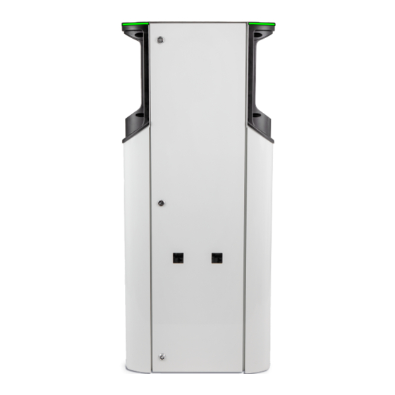
12. Dimensional drawings EVF200 Charging station with two charging points. Type label EVTL32.00 Ground mounting box (accessory) RAK112B_ENG / 2023-06-27 31 / 40... - Page 32 EVF300 Charging station with two charging points and a distribution cabinet. EVTL35.00 Ground mounting box (accessory) Distribution cabinet depth 160 mm Mounting plate inside the cabinet width 350 mm height 1250 mm RAK112B_ENG / 2023-06-27 32 / 40...
-
Page 33: Installation / Commissioning Checklist
13. Installation / Commissioning checklist Introduction Examine the mechanical and electrical installation in accordance with this checklist to make sure that the charging station is properly installed. Checking the Installation Examine the visual, mechanical and electrical installation when the charging station is un- powered. -
Page 34: Maintenance / Preventive Maintenance Instructions
14. Maintenance / Preventive maintenance instructions Recommended 1 x per year, take into consideration local regulations and national standards. Protect the charging station against pollution (water, snow, dust). WARNING Danger of electrical shock or injury! Risk of fire! Disconnect power before working inside the device or removing any components. MAINTENANCE ACTION Retighten all the screws on electric components. -
Page 35: Testing Instructions For The Electric Protective Device
15. Testing instructions for the electric protective device Press the TEST button. • The rocker turns to 0 position. • Turn the rocker back to I position. • • If a fault occurs, contact an electrician. 16. Troubleshooting Charging station is off, no lights on Issue Corrective action Mains voltage does not exist in supply con-... -
Page 36: Warranty
17. Warranty Warranty conditions, see www.ensto.com/building-systems 18. Declaration of Conformity The EU declaration of conformity is available at the following internet address: https://evwiki.ensto.technology/display/CHWI/Certificates 19. Disposal Do not dispose of electrical and electronic devices including their accessories with the household waste. -
Page 37: User Guide
User Guide 20. User Interfaces LED indicator lights will show the status of the charging point as described below: Charging point’s status LED light LED operation The charging point is free and ready to use Green Stable RFID read, authorization ongoing Green Flashing Charging authorization rejected... -
Page 38: Charging With Rfid
21.2. Charging with RFID You must have an RFID tag which has a permission to access the charging point. Start Charging with RFID Plug the charging cable to your electric vehicle. Plug the charging cable to the charging point. Show the RFID tag to the RFID reading area. While the RFID tag is read, the LED indicator flashes green and verifies the user permission to charge. - Page 39 RAK112B_ENG / 2023-06-27 39 / 40...
- Page 40 Ensto Chago Oy Ensio Miettisen katu 2, P.O. Box 77 FIN-06101 Porvoo, Finland Tel. +358 204 76 21 www.ensto.com/building-systems...
Need help?
Do you have a question about the Pro EVF200 and is the answer not in the manual?
Questions and answers