Advertisement
Quick Links
RAM 1500 PICK-UP TRUCK
Page | 1
Due to Clearview Continuous Improvement Program, information may change without notice.
Clearview takes no responsibility for the result of incorrect use of these installation instructions.
Year: 2020-Current
2015-2018
INSTALLATION & USER GUIDE
3 Frog Court, Craigieburn VIC 3064
(03) 8351 9933
info@clearviewaccessories.com.au
www.clearviewmirrors.com.au
PB-DG-001
PB-TA-001
April 2018
Advertisement

Related Manuals for ClearView PowerBoards PB-DG-001


Summary of Contents for ClearView PowerBoards PB-DG-001
- Page 1 3 Frog Court, Craigieburn VIC 3064 (03) 8351 9933 info@clearviewaccessories.com.au www.clearviewmirrors.com.au Page | 1 Due to Clearview Continuous Improvement Program, information may change without notice. Clearview takes no responsibility for the result of incorrect use of these installation instructions. April 2018...
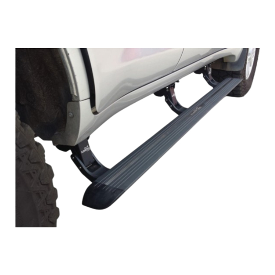
- Page 2 Power Boards will revolutionise your travel experience. Clearview Power Boards are triggered by the vehicle’s door sensor, so when the door opens, they drop to a convenient stepping height and when the door closes, they retract. With 300kg load capacity, safety cut off feature and IP68 rating on the motors, accessing your vehicle is as easy as one step up.
- Page 3 M10 Bolt, tighten the Bolt until the Nutsert deforms and locks into the Sill Panel. Repeat for 3 Nutserts on both sides of the vehicle. Page | 3 Due to Clearview Continuous Improvement Program, information may change without notice. Clearview takes no responsibility for the result of incorrect use of these installation instructions. April 2018...
- Page 4 M8 Hex Head Flange Bolts x 6 M8 Flange Nuts x 6 Page | 4 Due to Clearview Continuous Improvement Program, information may change without notice. Clearview takes no responsibility for the result of incorrect use of these installation instructions. April 2018...
- Page 5 Board is in central position before final tightening of the bolts. Page | 5 Due to Clearview Continuous Improvement Program, information may change without notice. Clearview takes no responsibility for the result of incorrect use of these installation instructions. April 2018...
- Page 6 PB-TA-001 Installing control unit and wiring IMPORTANT Clearview recommend this to be completed by a professional. Incorrect installation may cause damage to your vehicle and possible personal injuries. Position ECU and Wiring Harnesses 1. Remove felt panel located under the Glove Box. (Need plastic removal tool.) 2.
- Page 7 8. Plug the wiring harnesses back into the rear of the ECU and position the ECU onto the base of the Glove Box Opening, as shown above. Page | 7 Due to Clearview Continuous Improvement Program, information may change without notice. Clearview takes no responsibility for the result of incorrect use of these installation instructions. April 2018...
- Page 8 12. Connect the Power Wiring Plug to the corresponding ECU Plug and to the Vehicle Battery inside the Engine Compartment Page | 8 Due to Clearview Continuous Improvement Program, information may change without notice. Clearview takes no responsibility for the result of incorrect use of these installation instructions. April 2018...
- Page 9 Manual Operation: On occasions you may want the Clearview Power Boards to be deployed even when vehicle door is closed to access vehicle roof. To do this, open vehicle door first so Clearview Power Boards are deployed. Step your foot on the running board and close your vehicle door at the same time, the Clearview Power Board should remain deployed.
Need help?
Do you have a question about the PowerBoards PB-DG-001 and is the answer not in the manual?
Questions and answers