Sign In
Upload
Manuals
Brands
Texas Instruments Manuals
Motherboard
ADS8354EVM-PDK
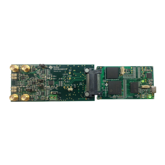
Texas Instruments ADS8354EVM-PDK Board Manuals
Manuals and User Guides for Texas Instruments ADS8354EVM-PDK Board. We have
2
Texas Instruments ADS8354EVM-PDK Board manuals available for free PDF download: User Manual
Texas Instruments ADS8354EVM-PDK User Manual (29 pages)
Evaluation Module
Brand:
Texas Instruments
| Category:
Motherboard
| Size: 3 MB
Table of Contents
Table of Contents
2
Overview
3
ADS8354EVM-PDK Features
3
ADS8354EVM Features
3
Related Documentation from Texas Instruments
3
Table 1-1. Related Documentation
3
Analog Interface
4
Connectors for Analog Inputs
4
Circuit
4
Table 2-1. Analog Input Connector Description
4
ADC Input Signal Driver
5
Figure 2-1. ADS8354EVM Analog Input Path
5
Figure 2-2. ADS8354EVM Common-Mode Voltage Buffer
6
Digital Interfaces
7
SPI for the ADC Digital I/O
7
Figure 3-1. ADS8354EVM Debug Header
7
Power Supplies
8
ADC Input Driver Configuration
8
ADC Voltage Reference Configuration
8
Table 4-1. Jumper Settings for ADC Input Driver Configuration
8
ADS8354EVM-PDK Initial Setup
9
Default Jumper Settings
9
Figure 5-1. ADS8354EVM-PDK Jumper Locations
9
Table 5-1. Default Jumper Configurations
9
EVM Graphical User Interface Software Installation
10
Figure 5-2. Ads835Xevm Software Installation
10
Figure 5-3. Device Driver Installation Wizard Prompts
11
Figure 5-4. Labview Run-Time Engine Installation
12
Figure 5-5. ADS8354EVM-PDK Installation Final Step
12
ADS8354EVM-PDK Operation
13
Figure 6-1. EVM-PDK Hardware Setup and LED Indicators
13
Figure 6-2. Launch the EVM GUI Software
13
EVM GUI Global Settings for ADC Control
14
Figure 6-3. EVM GUI Global Input Parameters
14
Time Domain Display Tool
15
Figure 6-4. Time Domain Display Tool Options
15
Spectral Analysis Tool
16
Figure 6-5. Spectral Analysis Tool
16
Table 6-1. External Source Requirements for Device Evaluation (SNR and THD)
16
Histogram Analysis Tool
17
Figure 6-6. Histogram Analysis Tool
17
Bill of Materials, Printed-Circuit Board Layout, and Schematics
18
Bill of Materials
18
Table 7-1. ADS8354EVM Bill of Materials
18
PCB Layout
20
Figure 7-1. ADS8354EVM PCB Layer 1: Top Layer
20
Figure 7-2. ADS8354EVM PCB Layer 2: GND
20
Figure 7-3. ADS8354EVM PCB Layer 3: Power Plane
20
Figure 7-4. ADS8354EVM PCB Layer 4: Bottom Layer
20
Schematics
21
Figure 7-5. Schematic Diagram (Page 1): EEPROM, Power
21
Figure 7-6. Schematic Diagram (Page 2): Analog Inputs, ADC Main, External Reference, PHI Connector
22
Figure 7-7. Schematic Diagram (Page 3): Hardware Components
23
Advertisement
Texas Instruments ADS8354EVM-PDK User Manual (35 pages)
Brand:
Texas Instruments
| Category:
Motherboard
| Size: 9 MB
Table of Contents
Table of Contents
2
Overview
3
EVM Analog Interface
3
Adsxx54Evm Analog Interface Input Connections
4
JP1 to JP4: Analog Interface Connections
4
SMA Analog Interface Connections
4
THS4521 Fully-Differential Amplifier Driver
5
Analog Input Range Jumper Settings
5
REF5025 2.5-V External Reference Source and OPA2350 Reference Driver
6
Digital Interface
7
Connector J6 Pinout
7
Power Supplies
8
Power-Supply Jumpers
8
Adsxx54Evm-PDK Initial Setup
9
Adsxx54Evm Default Jumper Settings
9
Default Jumper Configuration
9
Bottom View of SDCC Board with Microsd Memory Card Installed
10
Connecting Adsxx54Evm Board to SDCC Controller Board
11
LED Indicators on the SDCC Board
11
Welcome Screen and Destination Directory Screens
12
License Agreement and Start Installation Screens
12
Progress Bar and Installation Complete Screens
13
Windows 7 Driver Installation Warning
13
SDCC Device Driver Installation
14
SDCC Device Driver Completion
14
Adsxx54Evm-PDK Kit Operation
15
GUI Display Prompt
15
Open the Adsxx54Evm Settings Page
16
Selecting the External Onboard Reference or the Adsxx54 Internal Dual Reference
16
Programming the REFDAC Registers in the Adsxx54Evm
17
Range or ±2 × V
17
Range
17
Device Registers Page
18
Open the Data Monitor Page on the GUI
18
Data Monitor Page
19
Saving Data to a Text File
20
FFT Performance Analysis Page
21
Histogram Analysis Page
23
Open the GUI Settings Page
24
Set Capture Mode to SDCC Interface While Using the EVM Hardware
24
Bill of Materials, PCB Layout, and Schematics
25
Adsxx54Evm Bill of Materials
25
Adsxx54Evm PCB: Top Layer
27
Adsxx54Evm PCB: Ground Layer
27
Adsxx54Evm PCB: Power Layer
28
Adsxx54Evm PCB: Bottom Layer
28
Advertisement
Related Products
Texas Instruments ADS8353EVM-PDK
Texas Instruments ADS8350EVM-PDK
Texas Instruments ADS8383EVM
Texas Instruments ADS8364EVM
Texas Instruments ADS8380EVM
Texas Instruments ADS8370EVM
Texas Instruments ADS8361 EVM
Texas Instruments ADS8339
Texas Instruments ADS8332EVMV2-PDK
Texas Instruments ADS8339EVM
Texas Instruments Categories
Motherboard
Control Unit
Microcontrollers
Computer Hardware
Calculator
More Texas Instruments Manuals
Login
Sign In
OR
Sign in with Facebook
Sign in with Google
Upload manual
Upload from disk
Upload from URL