Table of Contents
Advertisement
Quick Links
OPERATING INSTRUCTIONS AND
SYSTEM DESCRIPTION FOR THE
BF-48DGX
DIFFERENTIAL AMPLIFIER /
FILTER MODULE
FOR EPMS SYSTEMS
VERSION 2.2
npi 2015
npi electronic GmbH, Bauhofring 16, D-71732 Tamm, Germany
Phone +49 (0)7141-9730230; Fax: +49 (0)7141-9730240
support@npielectronic.com; http://www.npielectronic.com
Advertisement
Table of Contents

Related Manuals for NPI BF-48DGX


Summary of Contents for NPI BF-48DGX
- Page 1 OPERATING INSTRUCTIONS AND SYSTEM DESCRIPTION FOR THE BF-48DGX DIFFERENTIAL AMPLIFIER / FILTER MODULE FOR EPMS SYSTEMS VERSION 2.2 npi 2015 npi electronic GmbH, Bauhofring 16, D-71732 Tamm, Germany Phone +49 (0)7141-9730230; Fax: +49 (0)7141-9730240 support@npielectronic.com; http://www.npielectronic.com...
-
Page 2: Table Of Contents
EPMS-07, EPMS-E-07 and EPMS-H-07 ................. 6 EPMS-07 and EPMS-H-07 ....................6 EPMS-E-07 ........................6 EPMS-03 .......................... 6 3. BF-48DGX Differential Amplifier / Filter Module .............. 7 3.1. BF-48DGX Components ....................7 3.2. BF-48DGX System Description ..................7 3.3. Signal Flow Diagram ......................8 3.4. -
Page 3: Safety Regulations
VERY IMPORTANT: Instruments and components supplied by npi electronic are NOT intended for clinical use or medical purposes (e.g. for diagnosis or treatment of humans), or for any other life-supporting system. npi electronic disclaims any warranties for such purpose. Equipment supplied by npi electronic must be operated only by selected, trained and adequately instructed personnel. -
Page 4: Epms-07 Modular Plug-In System
2.1. General System Description / Operation The npi EPMS-07 is a modular system for processing of bioelectrical signals in electrophysiology. The system is housed in a 19” rack-mount cabinet (3U) has room for up to 7 plug-in units. The plug-in units are connected to power by a bus at the rear panel. -
Page 5: Epms-03
Note: The chassis of the PWR-03D is connected to protective earth, and it provides protective earth to the EPMS-E housing if connected. Figure 3: Left: PWR-03D front panel view Right: PWR-03D rear panel view. Note: This power supply is intended to be used with npi EPMS-E systems only. version 2.2 page 5... -
Page 6: System Grounding
BF–48DGX User Manual 2.7. System Grounding EPMS-07/EPMS-03 The 19" cabinet is grounded by the power cable through the ground pin of the mains connector (= protective earth). In order to avoid ground loops the internal ground is isolated from the protective earth. The internal ground is used on the BNC connectors or GROUND plugs of the modules that are inserted into the EPMS-07 housing. -
Page 7: Bf-48Dgx Differential Amplifier / Filter Module
3.2. BF-48DGX System Description The BF-48DGX differential amplifier / filter is a plug-in unit for the npi EPMS-07 modular system. The BF-48DGX is designed to amplify and filter small bio-electrical signals. The input voltage range is ±12 V. Two overload-LEDs indicate if the linear region of the amplifier is exceeded. -
Page 8: Signal Flow Diagram
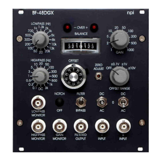
The position of the GAIN switch and of the FILTER switch(es) can be read from the respective monitor outputs (1V / step). 3.3. Signal Flow Diagram The signal is passed through the BF-48DGX as shown below. 3.4. Description of the Front Panel Figure 5: BF-48DGX front panel view version 2.2... - Page 9 BF–48DGX User Manual In the following description of the front panel elements each element has a number that is related to that in Figure 5. The number is followed by the name (in uppercase letters) written on the front panel and the type of the element (in lowercase letters). Then, a short description of the element is given.
- Page 10 BF–48DGX User Manual (6) LOWPASS FILTER switch 16 position rotary switch for selecting the corner frequency of the LOWPASS FILTER (range: 20 Hz to 20 kHz). The LOWPASS FILTER can be bypassed using switch (17). (7) (9) +/- OVER LEDs LEDs that indicate if the amplifier is 10% below its positive or negative limit (±10 V).
- Page 11 BF–48DGX User Manual (13, 15) DC / 0 / AC switch The position of the input coupling switch decides how the input signal is coupled: the input signal is AC coupled with a corner frequency of 0.1 Hz the input signal is DC coupled the input signal is grounded Switch to select the coupling of an incoming signal (AC or DC).
-
Page 12: Literature
BF–48DGX User Manual 4. Literature Boulton, A. A., Baker, G. B. & Vanderwolf, C. H. (eds.) (1990) Neurophysiological Techniques, Basic Methods and Concepts, Humana Press, Clifton, New Jersey. Kettenmann, H. & Grantyn, R. (eds.) (1992). Practical Electrophysiological Methods Wiley- Liss, New York. Ogden, D. -
Page 13: Technical Data
BF–48DGX User Manual 5. Technical Data INPUT Input range: ±12 V Input Impedance: 1 MΩ related to ground (other values possible), input capacitance: 30 pF AC coupling at input: corner frequency of 0.1 Hz (if AC /0 /DC switch at BNC connector is switched to AC) INPUT PROCESSING Offset Compensation:...
Need help?
Do you have a question about the BF-48DGX and is the answer not in the manual?
Questions and answers