Table of Contents
Advertisement
Quick Links
OPERATING INSTRUCTIONS AND
SYSTEM DESCRIPTION FOR THE
LHBF-48X
AMPLIFIER / FILTER SYSTEM
with 4-pole BESSEL filter
VERSION 2.1
npi 2014
npi electronic GmbH, Bauhofring 16, D-71732 Tamm, Germany
Phone +49 (0)7141-9730230; Fax: +49 (0)7141-9730240
support@npielectronic.com; http://www.npielectronic.com
Advertisement
Table of Contents

Related Manuals for NPI LHBF-48X


Summary of Contents for NPI LHBF-48X
- Page 1 OPERATING INSTRUCTIONS AND SYSTEM DESCRIPTION FOR THE LHBF-48X AMPLIFIER / FILTER SYSTEM with 4-pole BESSEL filter VERSION 2.1 npi 2014 npi electronic GmbH, Bauhofring 16, D-71732 Tamm, Germany Phone +49 (0)7141-9730230; Fax: +49 (0)7141-9730240 support@npielectronic.com; http://www.npielectronic.com...
-
Page 2: Table Of Contents
Table of Contents 1. Safety Regulations ......................3 2. LHBF-48X Components ..................... 4 3. LHBF-48X Amplifier / Filter ....................4 3.1. System Description ...................... 4 3.2. Signal Flow Diagram ....................4 3.3. Description of the Front Panel and Operation ............. 5 3.4. -
Page 3: Safety Regulations
General safety regulations for operating electrical devices should be considered. AC MAINS CONNECTION: While working with the npi systems, always adhere to the appropriate safety measures for handling electronic devices. Before using any device please read manuals and instructions carefully. -
Page 4: Lhbf-48X Components
LHBF-48X User Manual _______________________________________________________________________________________________________________ 2. LHBF-48X Components The following items are shipped with the LHBF-48X amplifier / filter: 3 LHBF-48X 19” cabinet 3 Power cord 3 User manual LHBF-48X Amplifier / Filter 3.1. System Description The LHBF-48X amplifier/filter is designed for processing small bio-electrical signals. The input voltage range is ±12 V. -
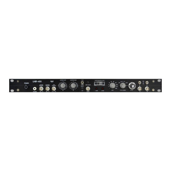
Page 5: Description Of The Front Panel And Operation
LHBF-48X User Manual _______________________________________________________________________________________________________________ 3.3. Description of the Front Panel and Operation Figure 2: LHBF-48X front panel view (the numbers are related to those in the text below) ___________________________________________________________________________ version 2.1 page 5... - Page 6 LHBF-48X User Manual _______________________________________________________________________________________________________________ In the following description of the front panel elements each element has a number that is related to that in Figure 2. The number is followed by the name (in uppercase letters) written on the front panel and the type of the element (in lowercase letters). Then, a short description of the element is given.
- Page 7 LHBF-48X User Manual _______________________________________________________________________________________________________________ OFFSET unit The OFFSET unit consists of OFFSET RANGE rotary switch (8) and OFFSET potentiometer (9). (8) OFFSET RANGE rotary switch 4-position rotary switch to set the RANGE of the OFFSET potentiometer (#9) (OFF, ±0.1 V, ±1 V, ±10V).
- Page 8 LHBF-48X User Manual _______________________________________________________________________________________________________________ The INPUTS can be used in single-ended or differential configuration. For single-ended operation connect the signal to be processed to the +IN or –IN connector and set the other (not used) input to ground using the respective toggle switch (set #11 or #12 to 0 position).
-
Page 9: Description Of The Rear Panel
LHBF-48X User Manual _______________________________________________________________________________________________________________ 3.4. Description of the Rear Panel Figure 3: LHBF-48X rear panel view (the numbers are related to those in the text below) (1) Mains connector Connector for mains. (2) Voltage selector Turning knob for selecting the mains voltage, 115 V or 230 V. -
Page 10: Technical Data
LHBF-48X User Manual _______________________________________________________________________________________________________________ 5. Technical Data Input: Input range: ±12 V Input impedance: 1 MΩ AC-coupling at input: Corner frequency of 0.1 Hz Differential input: CMR >90 dB Output: Full power bandwidth: 30 kHz Range of output: max. ±12 V Output impedance: 50 Ω...
Need help?
Do you have a question about the LHBF-48X and is the answer not in the manual?
Questions and answers