Advertisement
Quick Links
ADDENDUM FOR
SEC-05X
SINGLE ELECTRODE AMPLIFIER
SYSTEM
Information on the revised version of the SEC-05X amplifier – to be
used in conjunction with the SEC-05LX user manual
npi 2010
npi electronic GmbH, Hauptstrasse 96, D-71732 Tamm, Germany
Phone +49 (0)7141-9730230; Fax: +49 (0)7141-9730240
support@npielectronic.com; http://www.npielectronic.com
Advertisement

Related Manuals for NPI SEC-05X


Summary of Contents for NPI SEC-05X
- Page 1 ADDENDUM FOR SEC-05X SINGLE ELECTRODE AMPLIFIER SYSTEM Information on the revised version of the SEC-05X amplifier – to be used in conjunction with the SEC-05LX user manual npi 2010 npi electronic GmbH, Hauptstrasse 96, D-71732 Tamm, Germany Phone +49 (0)7141-9730230; Fax: +49 (0)7141-9730240...
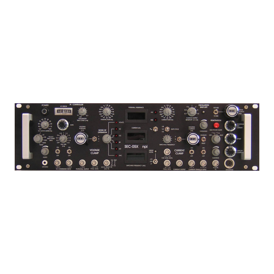
- Page 2 Compared to the SEC-05LX the SEC-05X amplifier is prepared already for additional operation modes. Therefore, some front panel elements changed slightly compared to the SEC-05LX. The MODE OF OPERATION switch has 6 positions. The active mode of operation is indicated by a red LED beneath the operation mode name.
- Page 3 SEC Systems with VCcCC Mode SEC Systems with DHC Mode SEC Systems with Linear Mode SEC Systems with Series Resistance Compensation VERSION 1.9 npi 2011 npi electronic GmbH, Hauptstrasse 96, D-71732 Tamm, Germany Phone +49 (0)7141-9730230; Fax: +49 (0)7141-9730240 support@npielectronic.com; http://www.npielectronic.com...
-
Page 4: Safety Regulations
VERY IMPORTANT: Instruments and components supplied by npi electronic are NOT intended for clinical use or medical purposes (e.g. for diagnosis or treatment of humans) or for any other life-supporting system. npi electronic disclaims any warranties for such purpose. Equipment supplied by npi electronic must be operated only by selected, trained and adequately instructed personnel. - Page 25 DISABLED 4 5 6 4 5 6 4 5 6 4 5 6 RESET RESET OFFSET OFFSET SWITCHING FREQUENCY SWITCHING FREQUENCY RISE TIME RISE TIME SEC-05LX npi SEC-05LX npi EXT. EXT. VOLTAGE VOLTAGE CURRENT CURRENT CLAMP CLAMP CLAMP CLAMP CAP.
-
Page 26: Controls And Connectors
CONTROLS AND CONNECTORS FRONT PANEL ELEMENTS 1 POWER POWER switch This switch turns on the power supply. The line fuse, line voltage selector and power cable connector are located on the rear panel. 2 VC ERROR VC ERROR display This analog display shows the error in the VC (voltage clamp) mode (command minus recorded potential). - Page 27 5, 6 DISPLAYS DISPLAYS (3 1/ digits, max. 1999) (MΩ Ω ) display: 5 POTENTIAL (mV) / R The upper display shows the recorded potential in mV (B; C; V modes) or the electrode resistance in M (R mode). 6 CURRENT (nA) display: The lower display shows the membrane current in nA (X.XX nA, 1.00 is 1.00 nA).
- Page 28 Mode select switch 12 can preset 3 modes: BUZZ mode: overcompensation of the capacity compensation effective in all four modes of operation (R, B, C, V modes). +Imax / -Imax modes: Application of maximum positive or negative current to the microelectrode (+/- 100 nA, standard headstage).
- Page 29 19 HOLDING POTENTIAL (mV) HOLDING POTENTIAL control and +/0/- POLARITY SWITCH (see also HOLDING CURRENT 21). The command signal for the voltage clamp mode (V mode) is a sum of following input signals: 19 HOLDING POTENTIAL (mV), with a +/0/- switch for selecting the polarity 30/ 32 analog input BNCs (/10mV;...
- Page 30 24 RISE TIME RISE TIME control Sometimes it is necessary to limit the rise time of a voltage clamp pulse especially in connection with PI-controllers to avoid overshooting of the potential. See also 3. 25 FREQUENCY MONITOR FREQUENCY MONITOR BNC connector The position of the POTENTIAL FILTER switch 4 is monitored at the FREQUENCY MONITOR BNC (-8...+7 Volt, 1 Volt / switch...
- Page 31 29 GROUND GROUND plug This connector is linked to the internal system ground, which has no connection to the 19" cabinet and the mains ground to avoid ground loops. Ground connectors are also on the rear panel (see REAR PANEL ELEMENTS, GND/EARTH connectors).
- Page 32 21 HOLDING CURRENT (nA): With this control a constant current can be generated,. The polarity is selected with a +/0- toggle switch near the control 40 1 nA/Volt Analog input (BNC connector). Calibration: 1 Volt = 1 nA 41 0.1 nA/V Analog input (BNC connector). Calibration: 1 volt = 100 pA Each input BNC is equipped with an on/off toggle switch that can be used to ground...
-
Page 33: Rear Panel Elements
REAR PANEL ELEMENTS SWITCHING OUTPUTS SWITCHING OUTPUTS (see Fig. 3) These outputs provide signals for tuning of the switched operation modes (V and C modes). In the V and C modes these signals are necessary for tuning the capacity compensation (see following chapter). - Page 34 POWER POWER / FUSE / LINE VOLTAGE SELECTOR / FUSE / LINE VOLTAGE SELECTOR The power chord is connected by a standardized coupling which comprises also the fuse, voltage selector and a line filter. With 230V AC the fuse must be 0.63A (slow), with 115V AC it must be 1.25A (slow).
- Page 35 REFERENCES General Brennecke, R. and Lindemann, B. (1971): A Chopped-Current Clamp for Current Injection and Recording of Membrane Polarization with Single Electrodes of Changing Resistance, T.I.T. Journal of Life Sciences, 1:53-58 Brennecke R, Lindemann B (1974) Theory of a membrane-voltage clamp with discontinuous feedback through a pulsed current clamp.
- Page 36 Kettenmann H, and R Grantyn (eds).Practical Electrophysiological Methods Willey-Liss, New York (1992). Misgeld U, Müller W, Polder HR (1989) Potentiation and suppression by eserine of muscarinic synaptic transmission in the guinea-pig hippocampal slice. J. Physiol. 409: 191-206 Müller, A., M. Bachmann, R. Berkels, S. Dhein, H.R. Polder and W. Klaus (1998) Switched single electrode amplifiers allow precise measurement of gap junction conductance, American Journal of Physiology, in press Ogden DC (1994) Microelectrode electronics.
- Page 37 Selected Literature About the npi SEC 05/10 Single Electrode Clamp Systems Recording Methods and Voltage Clamp Technique Dietzel, I. D., D. Bruns, H. R. Polder and H. D. Lux (1992) Voltage Clamp Recording, in Kettenmann, H. and R. Grantyn (eds.) Practical Electrophysiological Methods, Wiley-Liss, NY.
- Page 38 Leak subtraction Sutor, B., Zieglgänsberger, W. (1987): A low-voltage activated, transient calcium current is responsible for the time-dependent depolarizing inward rectification o f rat neocortical neurons in vitro. Pflügers Archiv 410: 102-111 Cardiac cells / double cell voltage clamp method Dhein, St.
- Page 39 Röhrig, G., Klausa, G., and Sutor, B. (1996) Intracellular acidification reduced gap junction coupling between immature neocortical pyramidal neurons, Journal Physiology 490.1 pp. 31-49 Single, S. and A. Borst (1998) Dendritic Integration and Its Role in Computing Image Velocity, Science. Vol. 281:1848-50 Single, S.
- Page 40 Selected Literature Voltage & Patch Clamp Techniques Publications in scientific journals: Armstrong, C.M. and Chow, R.H. (1987) Supercharging: A method for improving patch-clamp performance. Biophys.J. 52: 133-136. Bekkers, J.M. and Stevens, C.F. (1996) Cable properties of cultured hippocampal neurons determined from sucrose-evoked miniature EPSCs. J.Neurophysiol. 75: 1250-1255. Blanton, M.G., Lo Turco, J.J.
- Page 41 Henze, D.A., Cameron, W.E. and Barrionuevo, G.N. (1996) Dendritic morphology and its effects on the amplitude and rise-time of synaptic signals in hippocampal CA3 pyramidal cells. J.Comp.Neurol. 369: 331-344. Jackson, M.B. (1992) Cable analysis with the whole-cell patch clamp. Theory and experiment. Biophys.J.
- Page 42 Spruston, N., Jaffe, D.B., Williams, S.H. and Johnston, D. (1993) Voltage- and space-clamp errors associated with the measurement of electrotonically remote synaptic events. J.Neurophysiol. 70: 781-802. Spruston, N. and Johnston, D. (1992) Perforated patch-clamp analysis of the passive membrane properties of three classes of hippocampal neurons. J.
- Page 43 Book chapters : Armstrong, C. M. and Gilly, W.F. (1992) Access resistance and space clamp problems associated with whole-cell patch clamping. In: Methods in enzymology. Vol. 207, Academic Press, San Diego, CA, USA. Dietzel, I. D., Bruns, D., Polder, H. R. and Lux, H. D. (1992) Voltage clamp recording. In: Kettenmann, H.
- Page 44 Whole books: Boulton, A.A., Baker, G.B. and Vanderwolf, C.H. (eds.) (1990) Neurophysiological techniques. Basic methods and concepts. Humana Press, Clifton, New Jersey. Cole, K.S. (1968) Membranes ions and impulses. University of California Press, Berkely, CA. Ferreira, H.G. and Marshall, M.W. (1985) The biophysical basis of excitability. Cambridge University Press, Cambridge.
-
Page 45: Passive Cell Model
OPERATING INSTRUCTIONS AND SYSTEM DESCRIPTION FOR THE PASSIVE CELL MODEL FOR SINGLE ELECTRODE SWITCHED AMPLIFIERS VERSION 4.0 npi 2010 npi electronic GmbH, Hauptstrasse 96, D-71732 Tamm, Germany Tel. +49-(0)7141-9730230, Fax: +49-(0)7141-9730240 support@npielectronic.com; http://www.npielectronic.com... - Page 46 Passive Cell Model User Manual _________________________________________________________________________________________________________________ 1. Introduction The cell model is designed to be used to check the function of the SEC amplifier either 1. just after unpacking to see whether the instrument has been damaged during transport or 2.
- Page 47 Passive Cell Model User Manual _________________________________________________________________________________________________________________ Figure 2: Schematic diagram of the passive cell model 1.2. Connections and Operation Connections Turn POWER switch of the amplifier off. a) For simulation of an experiment using a suction electrode Connect the BNC jack of the cell model to the BNC connector P of the headstage.
- Page 48 Passive Cell Model User Manual _________________________________________________________________________________________________________________ Simulation of electrode in the bath Set switch #4, Figure 1 to the lower position. Set switch #5, Figure 1 to GROUND position. The 1 k resistor simulates the resistance of the bath solution. This can be used to train cancellation of offsets, using the bridge balance and using the capacity compensation.
- Page 49 APPENDIX TUNING CAPACITY COMPENSATION IN SEC AMPLIFIER SYSTEMS VERSION 1.11 For accurate measurements in switched mode, it is essential that the capacity of the electrode is fully compensated. Important: Wrong compensation of electrode capacity leads to errors in measurements done in switched mode of the amplifier (see Figure 2).
- Page 50 Tuning Capacity Compensation Criteria for the selection of the switching frequency Which are the most important criteria for the selection of the switching frequency? This question was analyzed in detail by M. Weckstrom and colleagues (4)(5). They presented a formula that describes the conditions for obtaining reliable results during a switching single electrode clamp: >...
-
Page 51: Tuning Procedure
Tuning Capacity Compensation Figure 2: Errors resulting from wrong compensation of the electrode capacity. Original data kindly provided by Ajay Kapur. For details see (7). Tuning Procedure (see also chapter “Getting Started”, pages 14, 15): First part: basic setting In SEC systems the capacity compensation of the electrode is split into two controls, the coarse control in the headstage and a the fine control at the front panel of the amplifier. - Page 52 Tuning Capacity Compensation Figure 3: Tuning of the coarse capacity compensation with an electrode (resistance100 M) in the bath. Time course of the signal at ELECTRODE POTENTIAL OUTPUT is shown (holding current: -1 nA, duty cycle: ¼, switching frequency: 2 kHz). Version 1.11 page 4...
- Page 53 Tuning Capacity Compensation Figure 4: Tuning of the coarse capacity compensation. Time course of the signal at ELECTRODE POTENTIAL OUTPUT is shown (holding current: -1 nA, duty cycle: ¼, switching frequency: 2 kHz). A model cell was connected (electrode resistance 100 M). Version 1.11 page 5...
- Page 54 Tuning Capacity Compensation Figure 5: Capacity compensation of the electrode in the bath (electrode resistance: 100 M, Current stimulus: 1 nA, duty cycle: ¼, switching frequency: 2 kHz). Current stimulus and electrode potential are shown. Version 1.11 page 6...
- Page 55 Tuning Capacity Compensation Figure 6: Capacity compensation of the electrode using a model cell (electrode resistance: 100 M, current: 1 nA, cell membrane: 100 M, 100 pF, duty cycle: ¼, switching frequency: 2 kHz). Current stimulus and membrane potential are shown. Version 1.11 page 7...
- Page 56 Tuning Capacity Compensation Second part: fine tuning Now the basic setting of the CAPACITY COMPENSATION is achieved. Since the electrode parameters change during the experiment (especially after impaling a cell), it is necessary to fine tune the CAPACITY COMPENSATION during the experiment using the CAP.COMP. control on the amplifier.
- Page 57 Tuning Capacity Compensation References: (1) Polder, H. R., Swandulla, D., Konnerth, A., & Lux, H. D. (1984). An Improved High Current Single-Electrode Voltage/Current Clamp System. Pflugers Arch. 402, R35. (2) Polder, H. R., & Swandulla, D. (2001). The use of control theory for the design of voltage clamp systems: a simple and standardized procedure for evaluating system parameters.
- Page 58 The npi single and two electrode current and voltage-clamp amplifiers (npi SEC 05X/10LX; npi TEC-05X series) have been modified in a way that slow membrane potential oscillations are exactly controlled by the voltage-clamp module without affecting faster responses, e.g.
- Page 59 Current Clamp Input The current clamp input (CURRENT STIMULUS BNC connector) is connected in the VCcCC mode in a way that fast current stimuli can be applied to the electrode. The condition for such recordings is a ratio of >1:1000 between current pulse duration and VCcCC time constant. Slow (long-lasting) current signals or DC (such as the HOLDING current) will be removed by the action of the VCcCC system.
- Page 60 SEC/TEC SYSTEMS WITH DHC MODE General Description The “Dynamic Hybrid Clamp” (DHC) mode is used for investigations of ionic conductances in voltage clamp (VC) mode following action potentials in current clamp (CC) mode. In CC mode an action potential is detected by a spike detector and triggers a timing unit. This timing unit sets a delay for triggering the SEC/TEC (being in CC mode).
- Page 61 Synchronization of Two or More SEC Amplifier Systems For recordings with two or more switched mode amplifiers in the same preparation it is necessary to synchronize the current injection and voltage recording timing protocols to avoid artifacts and excessive noise. This is done by the SYNCHRONIZATION inputs and outputs at the rear panel of the instruments based on a "master-slave"...
- Page 62 Important: All synchronized instruments must use the same duty cycle in switched VC or CC mode! If equipped with LIN mode, the LIN mode must not be enabled! Literature: Bedner, P., Niessen, H., Odermatt, B., Willecke, K., & Harz, H. (2003). A method to determine the relative cAMP permeability of connexin channels.
- Page 63 CALIBRATION of the x0.1 RANGE LOW VOLTAGE / LOW NOISE HEADSTAGE (Standard SEC SYSTEMS without Adapted Amplifier) This headstage has an output current range of 15nA into maximum 100 M, and the noise and bias current are reduced by a factor of 10 compared to the standard headstage. Therefore, it is recommended for whole cell patch clamp recordings.
- Page 64 CALIBRATION of the x0.1 RANGE LOW VOLTAGE / LOW NOISE HEADSTAGE (SEC SYSTEMS with Adapted Amplifier) This headstage has an output current range of 15nA into maximum 100 M, and the noise and bias current are reduced by a factor of 10 compared to the standard headstage. Therefore, it is recommended for whole cell patch clamp recordings.
- Page 65 Calibration of TEC-05X Amplifier with x10 Headstage GENERAL: The current range of the x10 low voltage headstage is the following: 1.2 µA into 10 M (max. output voltage is 12 V) All current related inputs and outputs must be multiplied by a factor of ten. This is valid for all four modes of operation (R , BR, CC, VC) Potential related signals are not affected.
- Page 66 SEC-EXT Headstage for Extracellular Recordings with npi SEC Systems The SEC-EXT headstage extends the range of operation of SEC amplifiers to the field of extracellular recordings. It has a differential high impedance input stage with capacity compensation for the non- inverting input (+ INPUT) and a gain of ten.
- Page 67 SEC SYSTEMS WITH LINEAR (x1 AND x10) MODE General Description The linear mode of the SEC amplifier is an “unswitched” operation mode of the SEC, working in voltage clamp (VC) and current clamp (CC). In contrast to standard patch clamp amplifiers the electrode voltage is nevertheless measured, also in VC.
- Page 68 SEC SYSTEMS WITH SERIES RESISTANCE COMPENSATION The SERIES RESISTANCE COMPENSATION (R compensation) unit consist of SERIES RESISTANCE COMP. potentiometer, and RS ON switch. The R compensation unit is functional if the LINEAR VC MODE is activated. It is not effective in all other modes of the amplifier. SER.
-
Page 69: Functional Description
The CAPACITY COMPENSATION control on the front panel can be used to improve the speed of response, it has also an impact on the stability of the feedback circuit. When starting the LIN VC session this control should be on a low value. The VC GAIN and INTEGRATOR controls have the same function as in switched VC mode.
Need help?
Do you have a question about the SEC-05X and is the answer not in the manual?
Questions and answers