
Subscribe to Our Youtube Channel
Related Manuals for True Fitness CS400-9


Summary of Contents for True Fitness CS400-9
- Page 1 * Assembly Guide & Warranty Card Included CS400 UPRIGHT BIKE OWNER’S MANUAL Revision 011514...
- Page 2 CS400 UPRIGHT BIKE OWNERS MANUAL IMPORTANT: All Products shown are prototype. Actual product delivered may vary. Product specifications, features & software are subject to change without notice. For the most up to date owner’s manual please visit www.truefitness.com. For documents in additional languages please visit www.truefitness.com/document-library/29/international-manuals IMPORTANTE: Todos los productos mostrados son prototipos.
- Page 3 CS400 UPRIGHT BIKE OWNERS MANUAL Frank Trulaske, founder and CEO of TRUE, has had the same simple philosophy of delivering superior products, service and support for over 30 years. Today, TRUE is the global leader in premium cardio equipment for the commercial and residential markets.
-
Page 4: Table Of Contents
CS400 UPRIGHT BIKE OWNERS MANUAL TABLE OF CONTENTS : Chapter 1: Safety Instructions Chapter 4B: Escalate Operation Safety Instructions Space Requirements Escalate 9 Overview Grounding Instructions Console Navigation Power Requirements Advanced Console Functions Warning Decals Compliances Chapter 4C: Emerge Operation Emerge Overview Chapter 2 Assembly Instructions Console Navigation... -
Page 5: Chapter 1: Safety Instructions
Do not modify the plug provided with this product. If it will not fit an electrical outlet, have a proper outlet installed by a qualified electrician. Your TRUE Fitness product must be properly grounded to reduce risk of shock if the bike malfunctions. Your bike is equipped with an electrical cord, which includes an equipment grounding conductor and a grounding plug. - Page 6 CHAPTER 1 SAFETY INSTRUCTIONS WARNING: To reduce the risk of burns, fire and electric shock or injury to persons, follow these instructions: • This appliance should never be left unattended when plugged in. • Do not use any type of extension cord with this product. •...
-
Page 7: Space Requirements
CHAPTER 1 SAFETY INSTRUCTIONS CAUTION (continued): • Use correct ergonomic positioning while operating the bike. • Do not allow animals on or near the equipment while in operation. • Do not exceed maximum user weight of 400 lbs (181 kg). •... -
Page 8: Grounding Instructions
CHAPTER 1 SAFETY INSTRUCTIONS GROUNDING INSTRUCTIONS: This product must be grounded, If it should malfunction or breakdown, grounding provides a path of least resistance for electric current to reduce the risk of electric shock. This product is equipped with a cord having an equipment-grounding conductor and a grounding plug. -
Page 9: Power Requirements
CHAPTER 1 SAFETY INSTRUCTIONS Truefitness.com / 800.426.6570 / 636.272.7100... -
Page 10: Warning Decals
CHAPTER 1 SAFETY INSTRUCTIONS WARNING DECALS: WARNING: Replace warning labels that may be worn, damaged or missing. To replace any worn or missing warning decals contact TRUE FITNESS by one of the following: www.truefitness.com or contact customer service at 800-883-8783. COMPLIANCES: This equipment complies with all applicable codes and regulations. -
Page 11: Chapter 2 Assembly Instructions
All exercise equipment is potentially hazardous. If attention is not paid to the conditions of equipment usage, death, or serious injury could occur. • Save these instructions. *Should you need technical assistance in assembly of your TRUE Fitness product, contact TRUE Fitness Technical Support at 1-800-883-8783. PRE-ASSEMBLY CHECK LIST: Provided Tools:... - Page 12 CHAPTER 2: ASSEMBLY INSTRUCTIONS PRE-ASSEMBLY CHECK LIST (CONTINUED): Provided Hardware: 1 & 2 (F & R 5 (F RONT TABILIZER RONT 6 (M 11 (S TORAGE 8 (H 12 (C ANDLEBAR ONSOLE OVERS Truefitness.com / 800.426.6570 / 636.272.7100...
-
Page 13: Assembly Steps
CHAPTER 2: ASSEMBLY INSTRUCTIONS BIKE ASSEMBLY STEPS: CAUTION: • Use caution when assembling bike. It is recommended that at least two people unpack and assemble bike. • Remove all bike components from packaging. • For each step use hardware in the corresponding bag Sub-Assembly Identification: Use the image below as a reference for where the provided sub-assemblies will be located in the complete bike assembly: Truefitness.com / 800.426.6570 / 636.272.7100... - Page 14 CHAPTER 2: ASSEMBLY INSTRUCTIONS BIKE ASSEMBLY STEPS (continued): Step 1 & 2 Front and Rear Stabilizer Bars: CAUTION: • It is recommended that at least 2 people are used to assemble the bike • To protect the floor from damage, rest the bike frame on a large piece of cardboard packaging •...
- Page 15 CHAPTER 2: ASSEMBLY INSTRUCTIONS BIKE ASSEMBLY STEPS (continued): Step 3 Seat Saddle: • Remove the flat washers and nuts from the 3 threaded rods on the bottom of the Seat Saddle • Insert Seat Saddle onto the Seat Post Mounting Plate; the threaded rods on the bottom of the Seat Saddle will align with the 3 openings on the Seat Post Mounting Plate •...
- Page 16 CHAPTER 2: ASSEMBLY INSTRUCTIONS BIKE ASSEMBLY STEPS (continued): Preparation for Step # 4 (continued): Prior to Routing the Front Mast Cables, it is very important that the IMPORTANT: following cable connection is confirmed. If this connection is not made, the Console will not be able to turn on. Truefitness.com / 800.426.6570 / 636.272.7100...
- Page 17 CHAPTER 2: ASSEMBLY INSTRUCTIONS BIKE ASSEMBLY STEPS (continued): Step #4 Front Mast Cable Routing: *Complete the power supply installation on page 23 prior to completing this step if this unit will be paired with a touchscreen or 15” TFT console. Pull-tie provided with the front mast (see image, above) NOTE: This connector is only used for the touchscreen console installation.
- Page 18 CHAPTER 2: ASSEMBLY INSTRUCTIONS BIKE ASSEMBLY STEPS (continued): Step #5 Front Mast: • For each screw, install through split washer then flat washer • Insert the Front Mast onto exposed bike frame U- bracket; pay special attention not to pinch any wires between the Front Mast and the frame •...
- Page 19 CHAPTER 2: ASSEMBLY INSTRUCTIONS BIKE ASSEMBLY STEPS (continued): Step #7 Handlebar Cable Routing: • While at least one person holds the Handlebar, another person should direct the Handlebar Cables through the Front Mast Step #8 Handlebar: • Insert the Handlebar U-bracket onto the Front Mast;...
- Page 20 CHAPTER 2: ASSEMBLY INSTRUCTIONS BIKE ASSEMBLY STEPS (continued): Step #9 Console Mounting: • The fasteners used to attach the Console are provided in the Console packaging • Align the back of the Console with the Front Mast Console Mounting Plate •...
- Page 21 CHAPTER 2: ASSEMBLY INSTRUCTIONS BIKE ASSEMBLY STEPS (continued): Step #10 Electronics Board Cable Connections : ANDLEBAR ABLE ONNECTIONS • Telemetry HR o 3-pin connector • Right Thumb Switch o 6-pin connector o not used on CS400 • CHR_(L) & CHR_(R) o Both 3-pin connector o It is acceptable to install either cable connector...
- Page 22 CHAPTER 2: ASSEMBLY INSTRUCTIONS BIKE ASSEMBLY STEPS (continued): Step #10A Cable Connections (console): *Follow Step 10A if installing a touchscreen console or 15”TFT console. For other consoles, proceed to Step 10B. 15” TFT 10” Touchscreen Console Console Network Power Cable Do Not Use 2 Pin Cable...
- Page 23 CHAPTER 2: ASSEMBLY INSTRUCTIONS BIKE ASSEMBLY STEPS (continued): Step #10A Cable Connections (console): *Follow Step 10A if installing a touchscreen console or 15”TFT console. For other consoles, proceed to Step 10B. 15” TFT 10” Touchscreen Console Console Do Not Use Ensure the Ground Cable is attached by the Ground Screw *Location Varies By Model...
- Page 24 CHAPTER 2: ASSEMBLY INSTRUCTIONS BIKE ASSEMBLY STEPS (continued): Step 10B Cable Connections (console): *Follow Step 10B if installing a 9” TFT console or an LED console. For other consoles, return to Step 10A. 9” TFT Console Orange LED Console Connect Data Cable (50-pin) Both 9”...
- Page 25 CHAPTER 2: ASSEMBLY INSTRUCTIONS BIKE ASSEMBLY STEPS (continued): Step #11 Storage Tray: • Insert the Storage Tray on top of the Front Mast Mounting Plate; pay special attention to make sure that the plastic lip of the Storage Tray is tucked underneath the bottom of the Console •...
- Page 26 CHAPTER 2: ASSEMBLY INSTRUCTIONS BIKE ASSEMBLY STEPS (continued): Step #13 Pedals: • Align the Left Pedal with the Left Crank and the Right Pedal with the Right Crank; pedals should be clearly labeled on the Pedal Strap • Secure each pedal to the appropriate crank using the provided wrench NOTE: The left pedal is reverse-threaded (turn counter-clockwise to tighten)
- Page 27 CHAPTER 2: ASSEMBLY INSTRUCTIONS BIKE ASSEMBLY STEPS (continued): Unit Leveling (if necessary): Turn feet (4x, located on the front and rear stabilizer) to adjust the levelness of the unit. Final Unit Connections: Truefitness.com / 800.426.6570 / 636.272.7100...
- Page 28 CHAPTER 2: ASSEMBLY INSTRUCTIONS BIKE ASSEMBLY STEPS (continued): Optional Touchscreen Console & 15” TFT Console Connections: Optional 9” TFT Console and Orange LED Console Connections: Truefitness.com / 800.426.6570 / 636.272.7100...
- Page 29 CHAPTER 2: ASSEMBLY INSTRUCTIONS BIKE ASSEMBLY STEPS (continued): IMPORTANT: The following steps are only required if this unit will be paired with a touchscreen console or 15” TFT Console. Power Supply Installation Step A (cable routing): Reconnect Disconnect Truefitness.com / 800.426.6570 / 636.272.7100...
- Page 30 CHAPTER 2: ASSEMBLY INSTRUCTIONS BIKE ASSEMBLY STEPS (continued): Power Supply Installation Step B (remove access plastic): • Remove the Access Plastic fasteners (quantity 3) with a Phillips head screwdriver (not provided) • Remove the Access Plastic Power Supply Installation Step C (remove wire tie): Remove wire-tie •...
- Page 31 CHAPTER 2: ASSEMBLY INSTRUCTIONS BIKE ASSEMBLY STEPS (continued): Power Supply Installation Step D (input plug connection): Raise Mast Boot (Optional) • Connect the Input Plug to the Power Supply • If necessary, the Mast Boot (installation step # 6) can be removed to allow more access to the Power Supply cable connections...
- Page 32 CHAPTER 2: ASSEMBLY INSTRUCTIONS BIKE ASSEMBLY STEPS (continued): Power Supply Installation Step D (secure the power supply): • Secure the Power Supply to the square frame tube using 2 wire-ties (positions shown, above) • Wire-ties should also secure the extra Power Supply •...
-
Page 33: Chapter 3: Product Overview
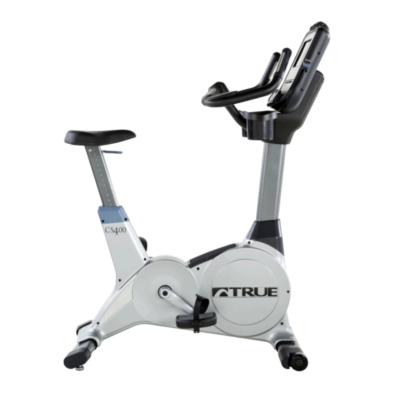
CHAPTER 3: PRODUCT OVERVIEW BIKE OVERVIEW: Console Assembly Contact Heart Rate Pads Bottle Holder Seat Adjustment Handle Coaxial Port Ethernet Port Power Cord Pedals Battery Charge Port Leveling Feet Truefitness.com / 800.426.6570 / 636.272.7100... - Page 34 CHAPTER 3: PRODUCT OVERVIEW BIKE OVERVIEW (continued): Console Assembly: The console allows the user to set up a workout program and control the bike during a workout (For console overview and operation instructions refer to the owner’s manual for the selected console option). Contact Heart Rate Pads: Allows the user to check their heart rate without wearing a wireless chest strap.
-
Page 35: Chapter 4: Programming & Operation Heart Rate Monitoring
CHAPTER 4: PROGRAMMING & OPERATION HEART RATE MONITORING: This bike can monitor a user’s heart rate using either a Polar® compatible chest strap or the metal grips on the hand rails (called contact heart rate or CHR pads). A chest strap transmits the user’s heart rate to the bike via radio, and the CHR pads connect to a special computer circuit to extract the user’s heart rate. - Page 36 CHAPTER 4: PROGRAMMING & OPERATION HEART RATE CONTROL (continued): The TRUE HRC system is unique because users must enter the key parameters of the workout; target heart rate, weight, age, and time, prior to beginning the HRC workout. As users approach their target heart rate, the bike’s computer takes full control over the workout and changes the workout intensity automatically to keep users near their target heart rate.
-
Page 37: Program Descriptions
CHAPTER 4: PROGRAMMING & OPERATION PROGRAM DESCRIPTIONS: Available programs vary depending on the console option selected. Please refer to the chart below for assistance in determining which programs are available on this unit. Console Options Transcend Escalate Emerge Quick Start: *** A workout in which the user controls all settings. - Page 38 CHAPTER 4: PROGRAMMING & OPERATION PROGRAM DESCRIPTIONS (continued): Single Hill: *** WORKLOAD increases to a maximum at the mid-point of the workout, then decreases to the finish to simulate one big hill. Random Hills: *** Users can adjust their A WORKLOAD profile that changes to simulate random hills. LEVEL at any time during the workout to increase or decrease the intensity of the hills.
- Page 39 CHAPTER 4: PROGRAMMING & OPERATION PROGRAM DESCRIPTIONS (continued): Custom Hill: * friendly setup screens allow users Easy to change WORKLOAD interval workouts that simulate hills. User to create any hill profile. Custom Ultra: ** If users are having trouble finding a workout that fits their specific needs, try setting up the Custom Ultra! This completely customizable workout setup allows WORKLOAD and PACE SETTER interval control as well as the ability to control interval time.
- Page 40 CHAPTER 4: PROGRAMMING & OPERATION PROGRAM DESCRIPTIONS (continued): Custom HRC Intervals: * Users s their et up own heart rate intervals. Specify WORK and REST targets and let the machine make all the – Users should their adjustments. The workout begins in MANUAL control gradually increase WORKLOAD until heart their...
-
Page 41: Virtual Active Videos
CHAPTER 4: PROGRAMMING & OPERATION VIRTUAL ACTIVE VIDEOS: * *Content is provided by Virtual Active™ and is subject to change without notice. Indoor Cycling Group World Tour Northern Italy: Northern Italy is a cyclist’s dream, where stunning views meet tough terrain. The rugged cliffs along Italy’s largest lake, Lago di Garda are just a short ride away from the idyllic small town of Pregasina, and the rural mountain passes of Gampenjoch are as beautiful as they are treacherous. - Page 42 CHAPTER 4: PROGRAMMING & OPERATION VIRTUAL ACTIVE VIDEOS (continued): American Southwest 2 Run: Return to the crimson cliffs of the Southwest. Scale Angel’s Landing in Zion National Park in Utah, surf “The Wave” in Arizona, and go all-in, with a sprint down the fabulous Las Vegas Strip in Nevada. The guided workout begins with a quick build and maintains a strong pace throughout.
-
Page 43: Chapter 4A: Transcend Operation
CHAPTER 4A: TRANSCEND OPERATION TRANSCEND OVERVIEW: Cooling Fan Touchscreen Display USB Jack Warning Decal 30 pin iPod® Headphone Jack Reading Rack Connector Truefitness.com / 800.426.6570 / 636.272.7100... - Page 44 CHAPTER 4A: TRANSCEND OPERATION CONSOLE OVERVIEW (continued): Touchscreen Display: A capacitive touchscreen used for workout control and feature navigation. 30 pin iPod® Connector: Standard 30 pin iPod connector used to connect an iPod to the console. Headphone Jack: Standard 3.5mm audio jack used to connect headphones to the console during media playback. USB Jack: Allows users to export workout data to an external USB drive or update the console software.
-
Page 45: Touchscreen Introduction
CHAPTER 4A: TRANSCEND OPERATION TOUCHSCREEN INTRODUCTION: The Transcend Console utilizes a fully integrated capacitive touch screen display and a multi-screen interface to provide a state of the art and user friendly workout. Capacitive touchscreen technology relies on the conductive properties of the human body to detect when and where on a display the user is touching. - Page 46 CHAPTER 4A: TRANSCEND OPERATION TOUCHSCREEN NAVIGATION (continued): Home Screen: The Home Screen is displayed on the console when there is no workout in progress. From this screen the user is able to select from various options to begin a workout or view media. A) Quick Start Starts a Quick Start workout in which the user controls all settings.
- Page 47 CHAPTER 4A: TRANSCEND OPERATION TOUCHSCREEN NAVIGATION (continued): Selecting a Preset Workout: Preset workouts are accessed by touching the Workout Finder Button on the home screen. Workouts are organized into 5 categories. To view the workouts in a category simply touch a Category Selection button (A) or swipe through categories in the category preview window (B).
- Page 48 CHAPTER 4A: TRANSCEND OPERATION TOUCHSCREEN NAVIGATION (continued): Workout Data Screens: During any workout a Workout Data Screen will be displayed to give the user a comprehensive visual overview of their current workout data. A) Custom Data Display #1: This display will toggle between multiple data points. To select which data points are displayed press the arrow below the Data Display to open the Selection Toolbox (A1) B) Workload Level: Displays the current Workload level.
- Page 49 CHAPTER 4A: TRANSCEND OPERATION TOUCHSCREEN NAVIGATION (continued): Workout Data Screen Controls: The Workout Data Screens contain controls that allow users to adjust settings during their workout A) Workload Control: Allows the user to manually increase or decrease the workload during a workout. C) Bike Mode: Engages Bike Mode, which simulates s riding a 21-speed road bike.
- Page 50 CHAPTER 4A: TRANSCEND OPERATION TOUCHSCREEN NAVIGATION (continued): Switching Between Workout Data Screens: There are several workout screens available to choose from. To switch between screens the user can touch the button selector (A) for the specific Workout Data Screen they wish to view or simply swipe their finger across the main display window (B) to scroll through the available screens.
-
Page 51: Ipod® Integration
CHAPTER 4A: TRANSCEND OPERATION iPod® INTEGRATION: The Transcend console has an advanced iPod® Integration feature which allows a user to connect their iPod® to the console via the 30 pin connector located on the front of the console. Once connected, the user can control the functions of their iPod®... -
Page 52: Tv Controls
CHAPTER 4A: TRANSCEND OPERATION TV CONTROLS: This console has an integrated HDTV Tuner which allows the user to watch live programming in crisp, clear high Definition. The TV controls are built in to a Workout Data Screen to allow the user to monitor their workout while enjoying their favorite shows. -
Page 53: Virtual Active
CHAPTER 4A: TRANSCEND OPERATION VIRTUAL ACTIVE®: Virtual Active® provides users with a scenic, first-person video to enhance a workout. The Workout Data Screen controls and displays are still available when using this feature in standard mode. The video can be stopped at any time during the program by touching the Stop Button (A). -
Page 54: Advanced Console Functions
WARNING: Misconfiguration of the console may cause damage to the unit and void the manufacturer warranty. If necessary, please contact TRUE Fitness Technical Support at 800-883-8783 for assistance. Entering Service Mode: Entering Service Mode can be completed by pressing and holding the TRUE logo (A) in the upper left corner of the home screen. - Page 55 CHAPTER 4A: TRANSCEND OPERATION ADVANCED CONSOLE FUNCTIONS (continued): Summary Screen: The Summary Screen will be the first screen displayed after entering service mode. This screen will give a general overview of the unit’s setup. *Changes cannot be made in this screen. A) Product Model: The model number that the console is currently configured to.
- Page 56 CHAPTER 4A: TRANSCEND OPERATION ADVANCED CONSOLE FUNCTIONS (continued): Setup Menu: The setup menu is accessed by touching the Setup button on the main menu. The Setup Menu is separated into seven sub- categories and allows to users configure the console and to set up various functions of the unit. Sub-Categories can be accessed by touching the selection buttons...
- Page 57 CHAPTER 4A: TRANSCEND OPERATION ADVANCED CONSOLE FUNCTIONS (continued): Setup Menu - Clock: Correctly setting up the clock will ensure that all workout data that is exported by a user will be correctly labeled. Correct time is also important for troubleshooting purposes when viewing the system’s error log. Setting the Clock: •...
- Page 58 CHAPTER 4A: TRANSCEND OPERATION ADVANCED CONSOLE FUNCTIONS (continued): Setup Menu - Screen Saver: Users can load JPG images to be used by the console as a custom screen saver. In order to be uploaded to the console, images will need to be placed on a USB drive in a folder named “screen saver” (case sensitive). Importing Screen Saver Images: •...
- Page 59 CHAPTER 4A: TRANSCEND OPERATION ADVANCED CONSOLE FUNCTIONS (continued): Setup Menu - Facility Images: The Transcend console supports customizable facility images to help promote specials, events or endorse a brand. In order to be uploaded to the console, images will need to be placed on a USB drive in a folder named “facility” (case sensitive). Importing Screen Saver Images: •...
- Page 60 CHAPTER 4A: TRANSCEND OPERATION ADVANCED CONSOLE FUNCTIONS (continued): Setup Menu - TV Setup: Transcend consoles have an integrated HDTV Tuner which allows the user to watch live programming in crisp, clear high Definition. Before any programming can be viewed, the TV signal needs to be set up. (TV Options will not be displayed on the Home Screen or in the Workout Data Screens until the TV Setup Steps have been completed) TV Setup Steps: •...
- Page 61 CHAPTER 4A: TRANSCEND OPERATION ADVANCED CONSOLE FUNCTIONS (continued): TV Setup Steps (continued): • When the console is finished scanning for channels, the Channel List (G) will be populated with the available channels. Individual channels can be removed by touching the channel in the Channel List (G) and then touching the Remove Channel button (H) or all Channels can be cleared by touching the Clear All Channels button (I).
- Page 62 CHAPTER 4A: TRANSCEND OPERATION ADVANCED CONSOLE FUNCTIONS (continued): Setup Menu - Network Setup: The Network Setup screen displays the current network information for the console (A) and allows for Netpulse® configuration (in a Netpulse® enabled environment), To Configure Netpulse: • From the Main Menu, press the Setup button.
- Page 63 CHAPTER 4A: TRANSCEND OPERATION ADVANCED CONSOLE FUNCTIONS (continued): Options Menu: The Options menu allows users to customize settings on the console to meet their needs. The settings in this menu save automatically. A) Metric Units: When enabled, the console will display all Metric units rather than American Standard. B) Save Workout Enabled: Turn on this feature to allow users to export workout data to USB devices.
- Page 64 CHAPTER 4A: TRANSCEND OPERATION ADVANCED CONSOLE FUNCTIONS (continued): Timers Menu: The Timers Menu allows for time limits to be set on various console features and functions. A) Cooldown Time: Use the slider to adjust the length of the cooldown segment at the end of a workout. B) Maximum Workout Time: This setting will limit the amount of time that all workouts can last (this setting does not apply to quickstart workouts, manual workouts or distance workouts).
- Page 65 CHAPTER 4A: TRANSCEND OPERATION ADVANCED CONSOLE FUNCTIONS (continued): Statistics Menu: The statistics menu provides an overview of how long the unit has been used. Touching the summary button (A) will provide a usage summary. Run Hours (B) is the total number of hours the unit has been used. Machine Distance (C) is the total distance in miles that the unit has traveled.
- Page 66 CHAPTER 4A: TRANSCEND OPERATION ADVANCED CONSOLE FUNCTIONS (continued): Diagnostics Menu: The Diagnostics Menu contains tools used to help diagnose errors and performance issues. The first screen displayed is Tests: A) Contact Heart Rate: Ensures the unit is receiving the data by displaying the user’s heart rate when the contact heart rate pads are gripped. B) Telemetry Heart Rate: Use a wireless heart rate strap or simulator to test if the unit is receiving wireless heart rate data.
- Page 67 CHAPTER 4A: TRANSCEND OPERATION ADVANCED CONSOLE FUNCTIONS (continued): Diagnostics Menu - Error Log: Touching the Error Log button (A) in the Diagnostics Menu, will display a time stamped list of recent fault codes that can be helpful in the troubleshooting process. The Error Log can be reset by touching the Clear button (B), but it is not recommended.
- Page 68 CHAPTER 4A: TRANSCEND OPERATION ADVANCED CONSOLE FUNCTIONS (continued): Diagnostics Menu - Software Update (continued) • Insert the USB drive containing the software update DEB file into the console’s USB port. • From the Main Menu, press the Diagnostics button. • From the Diagnostics Menu, press Software update button (A).
-
Page 69: Chapter 4B: Escalate 9 Operation
CHAPTER 4B: ESCALATE OPERATION ESCALATE OVERVIEW: LCD Display Selection Buttons Selection Buttons Workload Keys Start Stop Reading Warning Rack Decal iPod® Numeric Headphone USB Port Keypad Jack Connector Truefitness.com / 800.426.6570 / 636.272.7100... -
Page 70: Escalate 9 Overview
CHAPTER 4B: ESCALATE OPERATION ESCALATE OVERVIEW (continued): LCD Display: Used to monitor or control a work out and for feature navigation. Selection Buttons: Used to navigate menus and make selections via the LCD Display. Workload Keys: Manually increases or decreases the workout intensity. Start: Allows the user to begin a Quick Start workout or preset workout. -
Page 71: Console Navigation
CHAPTER 4B: ESCALATE OPERATION CONSOLE NAVIGATION: Home Screen: The Home Screen is displayed on the console when there is no workout in progress. From this screen the user is able to select from various options to begin a workout. A) Workout Finder Displays preset workouts categorized by goal focused categories. - Page 72 CHAPTER 4B: ESCALATE OPERATION CONSOLE NAVIGATION (continued): Selecting a Preset Workout: Preset workouts are accessed by selecting Workout Finder from the home screen. To view the workouts in a category, select the category (A) by using the Scroll Selection Buttons (B) and then press the Next Selection Button (C). *Press and hold the Next Selection Button to return to the previous screen.
- Page 73 CHAPTER 4B: ESCALATE OPERATION CONSOLE NAVIGATION (continued): Workout Data Screens: During any workout a Workout Data Screen will be displayed to give the user a comprehensive visual overview of their current workout data. A) Custom Data Display #1: By Default, this display will show the distance for the current workout. Users can also choose custom data points to be seen in this display.
- Page 74 CHAPTER 4B: ESCALATE OPERATION CONSOLE NAVIGATION (continued): Workout Data Screen Controls: The Workout Data Screens contain various controls that allow users to adjust workout settings and to customize their overall workout experience. These controls are accessed by pressing the Selection Button for the control they wish to use. A) Change View: Switches between the available Workout Data Screens.
- Page 75 CHAPTER 4B: ESCALATE OPERATION CONSOLE NAVIGATION (continued): D) Source: Toggles between available audio sources which include; iPod® (when connected via the 30 pin iPod® connector), TV (if your console is equipped with a Broadcast Vision receiver), and FM radio. When an audio source is selected the user is given control over volume (A), and channel adjustments (B).
- Page 76 CHAPTER 4B: ESCALATE OPERATION CONSOLE NAVIGATION (continued): F) Bike Mode: Engages Bike Mode, which simulates s riding a 21-speed road bike. The resistance changes to constant torque against the pedals and calculates speed (A) for a more realistic biking experience. Using the Workload Keys (B) will change the simulated gears (C).
-
Page 77: Advanced Console Functions
CHAPTER 4B: ESCALATE OPERATION ADVANCED CONSOLE FUNCTIONS: Entering Service Mode: Entering Service Mode can be completed by pressing and holding the upper left selection button (A) for 3-5 seconds or until the “Workout Finder” icon (B) blinks. When the “Workout Finder” icon blinks, release and hold the “Workout Finder”... - Page 78 CHAPTER 4B: ESCALATE OPERATION ADVANCED CONSOLE FUNCTIONS (continued): Summary Screen: The Summary Screen provides an overview of the unit’s current settings (values cannot be changed in this screen). A) Product Model: The model number that the console is currently configured to. B) Software Version: The current version of software that is installed on the console.
- Page 79 WARNING: Misconfiguration of the console may cause damage to the unit and void the manufacturer warranty. If necessary, please contact TRUE Fitness Technical Support at 800-883-8783 for assistance. Truefitness.com / 800.426.6570 / 636.272.7100...
- Page 80 CHAPTER 4B: ESCALATE OPERATION ADVANCED CONSOLE FUNCTIONS (continued): Utilities Menu - Software Update: TRUE periodically release software updates to ensure users enjoy the best workout experience available. To update the console software , create a folder called PROGRAMS (in all caps) on a blank USB drive and copy the two update .bin files in to the PROGRAMS folder, as shown below.
- Page 81 CHAPTER 4B: ESCALATE OPERATION ADVANCED CONSOLE FUNCTIONS (continued): Utilities Menu - B-Vision Setup: When equipped with the optional Broadcast Vision receiver, the Escalate console is capable of playing audio wirelessly from video sources that are equipped with a Broadcast Vision compatible wireless transmitter. To configure this feature, follow the steps below.
- Page 82 CHAPTER 4B: ESCALATE OPERATION ADVANCED CONSOLE FUNCTIONS (continued): Utilities Menu - B-Vision Setup (continued): 3. Plug headphones into the headphone jack on the console and wear them for the remaining steps. 4. Use the Channel Selection Buttons (D) to scroll through the available channels. 5.
- Page 83 CHAPTER 4B: ESCALATE OPERATION ADVANCED CONSOLE FUNCTIONS (continued): Options Menu: The options menu contains 12 Settings with various options available for each. To navigate the options menu, use the scroll selection buttons (A) to highlight the option to be changed (B) and use the Workload keys (C) to adjust the options. Once the changes are complete, press the back selection button (D) and the changes will be automatically saved.
- Page 84 CHAPTER 4B: ESCALATE OPERATION ADVANCED CONSOLE FUNCTIONS (continued): Options Menu (continued): Max Workout Time: This setting will limit the amount of time that all workouts can last. By choosing the “Off” setting, the time will be unlimited (this setting does not apply to manual workouts or distance workouts). Finder Timeout: Choose how long the Workout Finder remains on the screen without any user interaction.
- Page 85 CHAPTER 4B: ESCALATE OPERATION ADVANCED CONSOLE FUNCTIONS (continued): Diagnostics Menu - Calibration/Test & Production Test: These menus are currently not used on bikes or ellipticals. Diagnostics Menu - Error Log: Error codes are an important part of troubleshooting any issues with the unit. Any time an error occurs it is entered into the error log for review by a service professional.
-
Page 86: Chapter 4C: Emerge Operation
CHAPTER 4C: EMERGE OPERATION EMERGE OVERVIEW: Level LED Upper LED Lower LED RPM LED Display Display Display Display Workload Keys Start Stop Reading Warning Rack Decal USB Port Workout Enter HRC Cruise Finder Control Truefitness.com / 800.426.6570 / 636.272.7100... - Page 87 CHAPTER 4C: EMERGE OPERATION EMERGE OVERVIEW: Workload Keys: Manually increases or decreases the workout intensity. Start: Allows the user to begin a Quick Start workout or preset workout. Reading Rack: A ledge on the console can be used to hold a book, magazine, e-reader, or tablet computer during a workout. USB Port: Allows users to export workout data to an external USB drive or update the console software.
-
Page 88: Console Navigation
CHAPTER 4C: EMERGE OPERATION CONSOLE NAVIGATION: Selecting a Preset Workout: To begin a preset workout, press the Workout Finder button (A) until the desired program is shown in the Upper LED Display (B) and then press the Enter button (C). *To begin a Target HRC Workout, press the HRC Cruise Control button (D) followed by the Enter button (C) Workout Data Entry: Before beginning a preset workout, the console will ask the user for information in order to give more accurate workout... - Page 89 CHAPTER 4C: EMERGE OPERATION CONSOLE NAVIGATION (continued): Workout Summary: Workouts can be ended by the user pressing the Stop button (A) or by completing the time or distance in a preset workout. Once a workout has ended the console will display a workout Summary which will give the user an overview of their workout which includes;...
-
Page 90: Advanced Console Functions
CHAPTER 4C: EMERGE OPERATION ADVANCED CONSOLE FUNCTIONS: Entering Maintenance Mode: Press and Hold the + Workload Button (A) until the unit beeps (about 3 seconds). Then release the + Workload Key and Immediately press and hold the Enter Button (B) until the unit beeps again (about 3 seconds). Then release the Enter button and when the Upper LED Display (C) reads “Maintenance Mode”, press the Enter Button (B) to enter maintenance mode. - Page 91 CHAPTER 4C: EMERGE OPERATION ADVANCED CONSOLE FUNCTIONS (continued): Maintenance Mode Navigation (continued): Within a category users can scroll through available options using the + and - Workload Keys (A). Once the desired setting is shown in the Upper LED Display (B), press the Enter Button (C) to confirm the selection. After confirming the selection, the + and –...
- Page 92 CHAPTER 4C: EMERGE OPERATION ADVANCED CONSOLE FUNCTIONS (continued): Diagnostics: The diagnostics menu contains various settings as well as tools used to help diagnose errors and performance issues. Total time: Displays an accumulative count of the total number of hours the unit has been used. Sound: Toggles the sound on or off.
- Page 93 WARNING: Misconfiguration of the console may cause damage to the unit and void the manufacturer warranty. If necessary, please contact TRUE Fitness Technical Support at 800-883-8783 for assistance. Model: Used to make changes to the model to which the console is installed.
-
Page 94: Chapter 5: Care & Maintenance
It is important to perform the minor maintenance tasks described in this section. Failure to maintain the bike as described here could void the TRUE Fitness Warranty. To reduce the risk of electrical shock, always unplug the unit from its power source before cleaning or performing any maintenance tasks. -
Page 95: Other Scheduled Preventive Maintenance
Inspect and lubricate pedal threads on bike to prevent corrosion. CAUTION: Use only TRUE Fitness certified service providers. LONG TERM STORAGE: When the bike is not in use for any length of time, turn it off. Make sure that the power cord is unplugged from the power source and is positioned so that it will not become damaged or interfere with people or other equipment. -
Page 96: Chapter 6: Customer Service
CONTACTING SERVICE: TRUE Fitness recommends that you gather the serial number, model number, and a brief description of the reason for the request. After information has been gathered you may choose to contact your selling dealer or local service company to set an appointment. -
Page 97: Reporting Freight Claims Or Parts Damage
Obvious damage to external packaging / internal product. Please refuse the shipment and it will be returned to TRUE Fitness by the carrier. Contact the TRUE Fitness customer support team by calling 800.883.8783 or sales support team by calling 800.426.6570 Monday-Friday during normal business hours to notify us that the shipment has been refused. Once we have received the damaged shipment, a replacement shipment will be sent to you. -
Page 98: Chapter 7: Additional Information
No Power No power at wall outlet Use a voltmeter to verify power at wall outlet Optional ERP board damaged Contact True Fitness Customer Service Department Battery is discharged Charge the battery overnight with optional power supply Motor control board damaged... - Page 99 CHAPTER 7: ADDITIONAL INFORMATION TROUBLESHOOTING GUIDE (continued): Transmitter belt contacts are not Readjust the transmitter belt so that it is in full contact with making good contact with the the skin skin Contacts on the transmitter belt Moisten the contacts on the transmitter belt are not moist Transmitter belt is not within 3 Adjust your position on the belt so that you are within 3 foot...
- Page 100 CHAPTER 7: ADDITIONAL INFORMATION TROUBLESHOOTING GUIDE (continued): Power cycle Console Configure incorrectly Re-configure console The product configuration data has Fault CN02: Invalid Console failed validation checks (incline Incline Motor out of Console Configuration Contact dealer or ranges make no sense, etc.) range TRUE service Loose Cable...
-
Page 101: Specification Sheet
CHAPTER 7: ADDITIONAL INFORMATION P r e m i u m F i t n e s s E q u i p m e n t S i n c e 1 9 8 1 The all-new TRUE CS400 Upright Bike combines quality materials with smart design for an overall package that is unbeatable in performance and durability. - Page 102 CHAPTER 7: ADDITIONAL INFORMATION UPRIGHT TECHNICAL Power Source 110V, Self-Generating (with Emerge or Escalate ), 220V Option Available (with Transcend10 or Escalate SPECIFICATIONS Cord Length 10' (3.0M) Drive System Single Stage Drive System with Poly-V Belts Crank 3-Piece Forged Steel Crank System with Sealed Bearings Resistance Source Hybrid Self-Generating Brake Resistance Levels...
-
Page 103: Warranty Information
*TRUE Fitness shall parts of the TRUE product (the “Product”) listed below, under not warrant the performance of the heart rate system on its... - Page 104 CHAPTER 7: ADDITIONAL INFORMATION Commercial Limited Warranty CS400 Upright Bike Save Time and Register Online! Activate Multiple Warranties at www.truefitness.com/support CS400 UPRIGHT BIKE SERIAL NUMBERS: 1. This Limited Warranty can be processed only if the Warranty Registration Form is completed on-line; or if the attached form is filled in, signed by the original purchaser and mailed to TRUE The CS400 upright bike comes with two serial numbers;...
- Page 105 Please Note: Failure to register this product will result in no servicing or authorization of parts to be shipped. To mail your warranty information, please fill in the information below and mail to: Service Dept., TRUE Fitness, 865 Hoff Road, St.
Need help?
Do you have a question about the CS400-9 and is the answer not in the manual?
Questions and answers