
Related Manuals for True Fitness ES900


Summary of Contents for True Fitness ES900
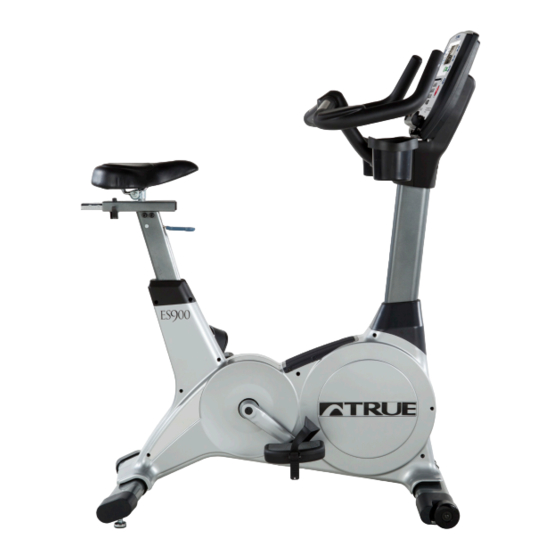
- Page 1 * Assembly Guide & Warranty Card Included ES900 UPRIGHT BIKE OWNER’S MANUAL Revision 123013...
- Page 2 ES900 UPRIGHT BIKE OWNERS MANUAL IMPORTANT: All Products shown are prototype. Actual product delivered may vary. Product specifications, features & software are subject to change without notice. For the most up to date owner’s manual please visit www.truefitness.com. For documents in additional languages please visit www.truefitness.com/document-library/29/international-manuals IMPORTANTE: Todos los productos mostrados son prototipos.
- Page 3 ES900 UPRIGHT BIKE OWNERS MANUAL Trulaske, founder and CEO of TRUE, has had the same simple philosophy of delivering superior products, service Frank and support for over 30 years. Today, TRUE is the global leader in premium cardio equipment for the commercial and residential markets.
-
Page 4: Table Of Contents
ES900 UPRIGHT BIKE OWNERS MANUAL TABLE OF CONTENTS : Chapter 1: Safety Instructions Chapter 4B: Emerge Operation Safety Instructions Emerge Overview & Navigation Space Requirements Advanced Console Functions Grounding Instructions Power Requirements Chapter 5: Care & Maintenance Warning Decals Care & Maintenance... -
Page 5: Chapter 1: Safety Instructions
Do not modify the plug provided with this product. If it will not fit an electrical outlet, have a proper outlet installed by a qualified electrician. Your TRUE Fitness product must be properly grounded to reduce risk of shock if the bike malfunctions. Your bike is equipped with an electrical cord, which includes an equipment grounding conductor and a grounding plug. - Page 6 Any changes or modifications to this equipment could void the product warranty. • To disconnect plug remove from electrical outlet. • Power adapter requirements for the ES900 are 110V AC input and 9V DC 1.5Amp output. • Use a TRUE AC power cord or AC/DC adapter only. •...
-
Page 7: Space Requirements
CHAPTER 1: SAFETY INSTRUCTIONS CAUTION (continued): • Avoid exiting bike while the pedals are still in motion. • Do use if you have a cold or fever. • When using this exercise machine, basic precautions should always be followed. • Use this bike only for its intended use as described in this manual. - Page 8 CHAPTER 1: SAFETY INSTRUCTIONS GROUNDING INSTRUCTIONS (continued): DANGER Improper connection of the equipment-grounding conductor can result in a risk of electric shock. • Check with a qualified electrician or serviceman if you are in doubt as to whether the product is properly grounded. Do •...
-
Page 9: Power Requirements
CHAPTER 1: SAFETY INSTRUCTIONS Truefitness.com / 800.426.6570 / 636.272.7100... -
Page 10: Warning Decals
CHAPTER 1: SAFETY INSTRUCTIONS WARNING DECALS: WARNING: Replace warning labels that may be worn, damaged or missing. To replace any worn or missing warning decals contact TRUE FITNESS by one of the following: www.truefitness.com or contact customer service at 800-883-8783. COMPLIANCES: This equipment complies with all applicable codes and regulations. -
Page 11: Chapter 2: Assembly Instructions
All exercise equipment is potentially hazardous. If attention is not paid to the conditions of equipment usage, death, or serious injury could occur. • Save these instructions. *Should you need technical assistance in assembly of your TRUE Fitness product, contact TRUE Fitness Technical Support at 1-800-883-8783. PRE-ASSEMBLY CHECK LIST: Provided Tools:... - Page 12 CHAPTER 2: ASSEMBLY INSTRUCTIONS PRE-ASSEMBLY CHECK LIST (continued): Provided Hardware: 1 & 2 (F & R 5 (F RONT TABILIZER RONT 6 (M 11 (S TORAGE 8 (H 12 (C ANDLEBAR ONSOLE OVERS Truefitness.com / 800.426.6570 / 636.272.7100...
- Page 13 CHAPTER 2: ASSEMBLY INSTRUCTIONS PRE-ASSEMBLY CHECK LIST (continued): Additional Items Provided: POLAR T34 Transmitter and Chest Strap (Heart Rate Monitor) Power Adaptor NOTE: For the 9” TFT Console, a different 12V, 3A Power Adaptor is provided with the console packaging. Truefitness.com / 800.426.6570 / 636.272.7100...
-
Page 14: Assembly Steps
CHAPTER 2: ASSEMBLY INSTRUCTIONS BIKE ASSEMBLY STEPS: CAUTION: • Use caution when assembling bike. It is recommended that at least two people unpack and assemble bike. • Remove all bike components from packaging. • For each step use hardware in the corresponding bag Sub-Assembly Identification: Use the image below as a reference for where the provided sub-assemblies will be located in the complete bike assembly: Truefitness.com / 800.426.6570 / 636.272.7100... - Page 15 CHAPTER 2: ASSEMBLY INSTRUCTIONS BIKE ASSEMBLY STEPS (continued): Step 1 & 2 Front and Rear Stabilizer Bars: CAUTION: • It is recommended that at least 2 people are used to assemble the bike • To protect the floor from damage, rest the bike frame on a large piece of cardboard packaging •...
- Page 16 CHAPTER 2: ASSEMBLY INSTRUCTIONS BIKE ASSEMBLY STEPS (continued): Step 3 Seat Saddle: • Attach the Seat Saddle to the Seat Post • Adjust Seat Saddle position • Tighten using the provided wrench Preparation for Step # 4: • Install the Mast Boot component (including rubber gasket) onto the Front Mast tube •...
- Page 17 CHAPTER 2: ASSEMBLY INSTRUCTIONS BIKE ASSEMBLY STEPS (continued): Step #4 Front Mast Cable Routing: Pull-tie provided with the front mast (see image, above) Truefitness.com / 800.426.6570 / 636.272.7100...
- Page 18 CHAPTER 2: ASSEMBLY INSTRUCTIONS BIKE ASSEMBLY STEPS (continued): Step #5 Front Mast: • For each screw, install through split washer then flat washer • Insert the Front Mast onto exposed bike frame U- bracket; pay special attention not to pinch any wires between the Front Mast and the frame •...
- Page 19 CHAPTER 2: ASSEMBLY INSTRUCTIONS BIKE ASSEMBLY STEPS (continued): Step #7 Handlebar Cable Routing: • While at least one person holds the Handlebar, another person should direct the Handlebar Cables through the Front Mast Step #8 Handlebar: • Insert the Handlebar U-bracket onto the Front Mast;...
- Page 20 CHAPTER 2: ASSEMBLY INSTRUCTIONS BIKE ASSEMBLY STEPS (continued): Step #9 Console Mounting: • The fasteners used to attach the Console are provided in the Console packaging • Align the back of the Console with the Front Mast Console Mounting Plate •...
- Page 21 CHAPTER 2: ASSEMBLY INSTRUCTIONS BIKE ASSEMBLY STEPS (continued): Step #10 Cable Connections (continued): Orange LED Console NOTE: Ethernet cable connection is not available on the Orange LED Console Truefitness.com / 800.426.6570 / 636.272.7100...
- Page 22 CHAPTER 2: ASSEMBLY INSTRUCTIONS BIKE ASSEMBLY STEPS (continued): Step #10 Cable Connections (continued): 9” TFT Console NOTE: Ethernet cable connection is not available on the 9” TFT Console Truefitness.com / 800.426.6570 / 636.272.7100...
- Page 23 CHAPTER 2: ASSEMBLY INSTRUCTIONS BIKE ASSEMBLY STEPS (continued): Step #11 Storage Tray: • Insert the Storage Tray on top of the Front Mast Mounting Plate; pay special attention to make sure that the plastic lip of the Storage Tray is tucked underneath the bottom of the Console •...
- Page 24 CHAPTER 2: ASSEMBLY INSTRUCTIONS BIKE ASSEMBLY STEPS (continued): Step #13 Pedals: • Align the Left Pedal with the Left Crank and the Right Pedal with the Right Crank; Pedals should be clearly labeled on the Pedal Strap • Secure each Pedal to the appropriate Crank using the provided wrench NOTE: The Left Pedal is reverse-threaded (turn counter-clockwise to tighten)
- Page 25 CHAPTER 2: ASSEMBLY INSTRUCTIONS BIKE ASSEMBLY STEPS (continued): Unit Leveling (if necessary): Turn feet (4x, located on the Front and Rear Stabilizer) to adjust the levelness of the unit. Final Unit Connections: Truefitness.com / 800.426.6570 / 636.272.7100...
-
Page 26: Chapter 3: Product Overview
CHAPTER 3: PRODUCT OVERVIEW BIKE OVERVIEW: Console Assembly Contact Heart Rate Pads Bottle Holder Seat Adjustment Handles Ethernet Port Power Cord Pedals Leveling Feet Truefitness.com / 800.426.6570 / 636.272.7100... -
Page 27: Bottle Holder
CHAPTER 3: PRODUCT OVERVIEW BIKE OVERVIEW (continued): Console Assembly: The console allows the user to set up a workout program and control the bike during a workout (For console overview and operation instructions refer to the owner’s manual for the selected console option). Contact Heart Rate Pads: Allows the user to check their heart rate without wearing a wireless chest strap. -
Page 28: Chapter 4: Programming & Operation Heart Rate Monitoring
CHAPTER 4: PROGRAMMING & OPERATION HEART RATE MONITORING: This bike can monitor a user’s heart rate using either a Polar® compatible chest strap or the metal grips on the hand rails (called contact heart rate or CHR pads). A chest strap transmits the user’s heart rate to the bike via radio, and the CHR pads connect to a special computer circuit to extract the user’s heart rate. -
Page 29: Target Heart Rate
CHAPTER 4: PROGRAMMING & OPERATION HEART RATE CONTROL (continued): The TRUE HRC system is unique because users must enter the key parameters of the workout; target heart rate, weight, age, and time, prior to beginning the HRC workout. As users approach their target heart rate, the bike’s computer takes full control over the workout and changes the workout intensity automatically to keep users near their target heart rate. -
Page 30: Program Descriptions
CHAPTER 4: PROGRAMMING & OPERATION PROGRAM DESCRIPTIONS: Available programs vary depending on the console option selected. Please refer to the chart below for assistance in determining which programs are available on this unit. Console Options Escalate Emerge Quick Start: ** A workout in which the user controls all settings. -
Page 31: Calorie Goal
CHAPTER 4: PROGRAMMING & OPERATION PROGRAM DESCRIPTIONS (continued): Glute Buster: * A changing WORKLOAD profile simulates hilly terrain to promote intense glute muscle use. Calorie Goal: ** This workout allows users to choose the number of calories they wish to burn within a specified workout time. The WORKLOAD will adjust automatically to attain this goal. - Page 32 CHAPTER 4: PROGRAMMING & OPERATION PROGRAM DESCRIPTIONS (continued): Target HRC: ** Users choose their target heart rate. The workout begins in MANUAL control – users should gradually increase the WORKLOAD until therir heart rate is within 10 bpm of their target. At this point, the machine takes control of WORKLOAD to maintain the user’s HR within a few beats of their target.
-
Page 33: Chapter 4A: Escalate 9 Operation
CHAPTER 4A: ESCALATE OPERATION ESCALATE OVERVIEW: LCD Display Selection Buttons Selection Buttons Decrease Increase Workload Workload Start Stop Reading Warning Rack USB Port Numeric Headphone 30 Pin iPod® Decal Keypad Jack Connector Truefitness.com / 800.426.6570 / 636.272.7100... -
Page 34: Escalate 9 Overview
CHAPTER 4A: ESCALATE OPERATION ESCALATE OVERVIEW (continued): LCD Display: Used to monitor or control a work out and for feature navigation. Selection Buttons: Used to navigate menus and make selections via the LCD Display. Workload Keys: Manually increases or decreases the workout intensity. Start: Allows the user to begin a Quick Start workout or preset workout. -
Page 35: Console Navigation
CHAPTER 4A: ESCALATE OPERATION CONSOLE NAVIGATION: Home Screen: The Home Screen is displayed on the console when there is no workout in progress. From this screen the user is able to select from various options to begin a workout. A) Workout Finder Displays preset workouts categorized by goal focused categories. -
Page 36: Console Navigation
CHAPTER 4A: ESCALATE OPERATION CONSOLE NAVIGATION (continued): Selecting a Preset Workout: Preset workouts are accessed by selecting Workout Finder from the home screen. To view the workouts in a category, select the category (A) by using the Scroll Selection Buttons (B) and then press the Next Selection Button (C). *Press and hold the Next Selection Button to return to the previous screen. -
Page 37: Console Navigation
CHAPTER 4A: ESCALATE OPERATION CONSOLE NAVIGATION (continued): Workout Data Screens: During any workout a Workout Data Screen will be displayed to give the user a comprehensive visual overview of their current workout data. A) Custom Data Display #1: By Default, this display will show the distance for the current workout. Users can also choose custom data points to be seen in this display. -
Page 38: Console Navigation
CHAPTER 4A: ESCALATE OPERATION CONSOLE NAVIGATION (continued): Workout Data Screen Controls: The Workout Data Screens contain various controls that allow users to adjust workout settings and to customize their overall workout experience. These controls are accessed by pressing the Selection Button for the control they wish to use. A) Change View: Switches between the available Workout Data Screens. -
Page 39: Console Navigation
CHAPTER 4A: ESCALATE OPERATION CONSOLE NAVIGATION (continued): D) Source: Toggles iPod® on or off (when connected via the 30 pin iPod® connector), When an audio source is selected the user is given control over volume adjustments (A) and the ability to skip tracks (B). E) Show Tools: Pressing the Show Tools Selection Button (A) will display various options. - Page 40 CHAPTER 4A: ESCALATE OPERATION CONSOLE NAVIGATION (continued): F) Bike Mode: Engages Bike Mode, which simulates riding a 21-speed road bike. The resistance changes to constant torque against the pedals and calculates speed (A) for a more realistic biking experience. Using the Workload Keys (B) will change the simulated gears (C).
-
Page 41: Advanced Console Functions
CHAPTER 4A: ESCALATE OPERATION ADVANCED CONSOLE FUNCTIONS: Entering Service Mode: Entering Service Mode can be completed by pressing and holding the upper left selection button (A) for 3-5 seconds or until the “Workout Finder” icon (B) blinks. When the “Workout Finder” icon blinks, release the upper right selection button and hold the “Workout Finder”... -
Page 42: Advanced Console Functions
CHAPTER 4A: ESCALATE OPERATION ADVANCED CONSOLE FUNCTIONS (continued): Summary Screen: The Summary Screen provides an overview of the unit’s current settings (values cannot be changed in this screen). A) Product Model: The model number that the console is currently configured to. B) Software Version: The current version of software that is installed on the console. -
Page 43: Advanced Console Functions
CHAPTER 4A: ESCALATE OPERATION ADVANCED CONSOLE FUNCTIONS (continued): Utilities Menu: The Utilities Menu allows users to adjust the time and date settings. Press the Enter Selection Button (A) to the time and date. Setting Time and Date: Use the Previous and Next Selection Buttons (A) to highlight the field to be changed. Then use the adjustment selection buttons (B) to adjust the selected value. -
Page 44: Advanced Console Functions
CHAPTER 4A: ESCALATE OPERATION ADVANCED CONSOLE FUNCTIONS (continued): Demo Mode: Demo mode is intended for use by sales professionals and should not be used in a home environment Diagnostics Menu: The Diagnostics menu will display the unit’s current usage data including total distance, in miles, that the unit has traveled as well as the total time, in hours, that the unit has been in use. - Page 45 CHAPTER 4A: ESCALATE OPERATION ADVANCED CONSOLE FUNCTIONS (continued): Options Menu: The options menu contains 5 Settings with various options available for each. To navigate the options menu, use the scroll selection buttons (A) to highlight the option to be changed (B) and use the + and - Selection Buttons (C) to adjust the options.
-
Page 46: Chapter 4B: Emerge Operation
CHAPTER 4B: EMERGE OPERATION EMERGE OVERVIEW & NAVIGATION: Upper LED Upper LED HRC Cruise Display Displays Numeric Keypad Control Decrease Increase Workload Workload Start Workout Change Enter Reading Warning Target Finder Display Rack Decal Truefitness.com / 800.426.6570 / 636.272.7100... - Page 47 CHAPTER 4B: EMERGE OPERATION EMERGE OVERVIEW & NAVIGATION (continued): Workload Keys: Manually increases or decreases the workout intensity. Start: Allows the user to begin a Quick Start workout or preset workout. Workout Finder: Pressing this button scrolls through available workouts. When the desired workout is displayed, the user must press start to begin the workout.
- Page 48 CHAPTER 4B: EMERGE OPERATION EMERGE OVERVIEW & NAVIGATION (continued): Upper LED Display: Shows the workout data of the program in progress in four value displays. Value Display Value Display Value Display Value Display Value Display #1 Value Display #2 Value Display #3 Value Display#4 Heart Rate –...
-
Page 49: Advanced Console Functions
ADVANCED CONSOLE FUNCTIONS: WARNING: Misconfiguration of the console may cause damage to the unit and void the manufacturer warranty. If necessary, please contact TRUE Fitness Technical Support at 800-883-8783 for assistance. Entering Diagnostics Mode: With the console powered up Press and hold the + WORKLOAD key for 10 seconds or until the console beeps. NOTE: If the sound is turned off no beep will be emitted from the console. -
Page 50: Chapter 5: Care & Maintenance
It is important to perform the minor maintenance tasks described in this section. Failure to maintain the bike as described here could void the TRUE Fitness Warranty. To reduce the risk of electrical shock, always unplug the unit from its power source before cleaning or performing any maintenance tasks. -
Page 51: Other Scheduled Preventive Maintenance
Inspect and lubricate pedal threads on bike to prevent corrosion. CAUTION: Use only TRUE Fitness certified service providers. LONG TERM STORAGE: When the bike is not in use for any length of time, turn it off. Make sure that the power cord is unplugged from the power source and is positioned so that it will not become damaged or interfere with people or other equipment. -
Page 52: Chapter 6: Customer Service
CONTACTING SERVICE: TRUE Fitness recommends that you gather the serial number, model number, and a brief description of the reason for the request. After information has been gathered you may choose to contact your selling dealer or local service company to set an appointment. -
Page 53: Reporting Freight Claims Or Parts Damage
Obvious damage to external packaging / internal product. Please refuse the shipment and it will be returned to TRUE Fitness by the carrier. Contact the TRUE Fitness customer support team by calling 800.883.8783 or sales support team by calling 800.426.6570 Monday-Friday during normal business hours to notify us that the shipment has been refused. Once we have received the damaged shipment, a replacement shipment will be sent to you. -
Page 54: Chapter 7: Additional Information
No Power No power at wall outlet Use a voltmeter to verify power at wall outlet Contact True Fitness Customer Service Department Optional ERP board damaged (if applicable) Charge the battery overnight with optional power supply Battery is discharged... - Page 55 CHAPTER 7: ADDITIONAL INFORMATION TROUBLESHOOTING GUIDE (continued): Malfunction Possible Cause Corrective Action Transmitter belt contacts are not Readjust the transmitter belt so that it is in full contact with making good contact with the the skin skin Contacts on the transmitter belt Moisten the contacts on the transmitter belt are not moist Transmitter belt is not within 3...
-
Page 56: Specification Sheet
P r e m i u m F i t n e s s E q u i p m e n t S i n c e 1 9 8 1 Go the distance in comfort on TRUE’s ES900. Ergonomic aero bars and armrests provide maximum body control, power and stability. - Page 57 CHAPTER 7: ADDITIONAL INFORMATION UPRIGHT TECHNICAL Power Source 110V/15A SPECIFICATIONS Cord Length 8' (2.4M) Drive Motor Single Stage Drive System with Poly-V Belts Crank 3-Piece Forged Steel Crank System with Sealed Bearings Resistance Source Eddy Current Brake Resistance Levels 25 (Emerge), 30 (Escalate &...
-
Page 58: Warranty Information
5. This Limited Warranty applies only to the cost of repair or replace- and necessary maintenance. *True Fitness shall not warrant the ment of parts and does not include labor (beyond the above warranty... - Page 59 TRUE. Even jobbing out warranty labor requires TRUE’s written approval. BIKE SERIAL NUMBERS: The ES900 upright bike comes with two serial numbers; one on the base and one on the display console (see diagram below). CONSOLE SERIAL The serial number on the base is located on bottom of the NUMBER: frame.
- Page 60 If you prefer to mail your warranty card, have the owner of the product complete the information below and return it to TRUE Fitness Technology within 30 days from the date of equipment installation.
Need help?
Do you have a question about the ES900 and is the answer not in the manual?
Questions and answers