KaVo ELECTROmatic TM Instructions For Use Manual
Hide thumbs
Also See for ELECTROmatic TM:
- Instructions for use manual (80 pages) ,
- Instructions for use manual (90 pages)
Table of Contents
Advertisement
Advertisement
Table of Contents

Related Manuals for KaVo ELECTROmatic TM


Summary of Contents for KaVo ELECTROmatic TM
- Page 1 Instructions for use ELECTROmatic TM and TMM/TMC...
- Page 2 Distributed by: Manufacturer: KaVo Dental GmbH Kaltenbach & Voigt GmbH Bismarckring 39 Bismarckring 39 88400 Biberach 88400 Biberach Germany Germany Tel. +49 7351 56-0 www.kavo.com Fax +49 7351 56-1488...
-
Page 3: Table Of Contents
Instructions for use ELECTROmatic TM and TMM/TMC Table of contents Table of contents 1 User instructions ........................ 6 1.1 User guide ........................6 1.1.1 Abbreviations ..................... 6 1.1.2 General marks and symbols................. 6 1.2 Target group ......................... 7 1.3 Service ......................... 7 1.3.1... - Page 4 Instructions for use ELECTROmatic TM and TMM/TMC Table of contents 4.7.3 Mount control panel on the side of a holder ............45 4.7.4 Mount control panel to cabinet/wall ..............47 4.8 Connecting the ELECTROmatic ..................48 4.9 Check the installation ..................... 48 5 Startup..........................
- Page 5 Instructions for use ELECTROmatic TM and TMM/TMC Table of contents 8.5 Storage ........................76 8.6 Service, inspection and testing after preparation ............... 76 9 Servicing ..........................77 9.1 Changing the filter - water inlet ..................77 9.2 Replacing the LED lamp of the KL 703 motor ..............78 9.3 Replacing the LED lamp of the COMFORTbase..............
-
Page 6: User Instructions
Read these instructions prior to first startup to avoid misuse and prevent dam- age. Requirement If other language versions are required, they can be requested from the cor- responding KaVo branch. Prior approval from KaVo must be obtained before copying and passing on the Instructions for Use. 1.1.1 Abbreviations Explanation... -
Page 7: Target Group
Instructions for use ELECTROmatic TM and TMM/TMC 1 User instructions | 1.2 Target group DANGER In cases which – if not prevented – directly lead to death or severe in- jury. WARNING In cases which – if not prevented – can lead to death or severe injury. -
Page 8: Terms And Conditions Of Warranty
KL 703 LED motor: 36 months from the date of purchase as confirmed by the salesperson. In case of justified complaints, KaVo will honour its warranty with a free re- placement or repair. The warranty does not cover defects and their consequences that arose or may... -
Page 9: Information On The Packaging: Storage And Transportation
Terms and Conditions, Art. 28). Outside Germany Note KaVo shall not be held liable for damage arising from transportation. The shipment must be checked on arrival. If the packaging is visibly damaged on delivery, please proceed as follows: 1. The recipient of the package must record the loss or damage on the delivery receipt. -
Page 10: Disposal
Any waste which is generated must be recycled or disposed of in strict com- pliance with all applicable national regulations in a manner which is safe both for people and the environment. If you have any questions regarding proper disposal of the KaVo product, please contact the KaVo branch. 10 / 90... -
Page 11: Disposal Of Electronic And Electrical Devices
According to EC directive 2012/19 concerning waste electrical and electronic equipment, this product is subject to the cited directive and must be disposed of accordingly within Europe. For more information, please visit www.kavo.com or contact your specialised dental dealers. For final disposal:... -
Page 12: Safety
Instructions for use ELECTROmatic TM and TMM/TMC 2 Safety | 2.1 Infection hazard 2 Safety The instructions for use are a component of the product and must be read care- fully prior to use and be accessible at all times. -
Page 13: Ingress Of Liquids
Defective high-speed handpieces can heat up strongly during use due to additional friction, especially in the head region, and possibly cause burn injuries. KaVo recommends to activate the SAFEdrive function during treatments inside the oral cavity in order to reduce the risk of burn injuries caused by defective high-speed handpieces. -
Page 14: Qualification Of Personnel
Repairs and safety checks may only be performed by trained service personnel. The following persons are authorised to do this: ▪ Service technicians of KaVo branches after the appropriate product training ▪ Service technicians of KaVo authorised dealers after the appropriate product training ▪... -
Page 15: Electromagnetic Fields
Instructions for use ELECTROmatic TM and TMM/TMC 2 Safety | 2.8 Electromagnetic fields 2.8 Electromagnetic fields Electromagnetic fields might interfere with the functions of implanted systems (such as pacemakers). Medical electrical devices are subject to special precautions regarding electro- magnetic compatibility and must be installed and operated in accordance with the tables of electromagnetic compatibility. -
Page 16: Description Of The Product
▪ ELECTROmatic TMC with one INTRA LUX Motor KL 703 and one COMFORTdrive See also: 2 3.2 Scope of delivery, Page 17 The various product versions of the ELECTROmatic TM, TMM and TMC are de- scribed below. The descriptions apply to all product versions, unless explicitly stated otherwise. 3.1 Intended use... -
Page 17: Scope Of Delivery
Instructions for use ELECTROmatic TM and TMM/TMC 3 Description of the product | 3.2 Scope of delivery 3.2 Scope of delivery Figure Material num- ELECTROmatic TM ELECTROmatic TMM/TMC ELECTROmatic ELECTROmatic ELECTROmatic Control unit 1.011.2100 Control unit 1.011.2600 1.011.8054 Cover panel 1.011.7165... - Page 18 Instructions for use ELECTROmatic TM and TMM/TMC 3 Description of the product | 3.2 Scope of delivery Figure Material num- ELECTROmatic TM ELECTROmatic TMM/TMC ELECTROmatic ELECTROmatic ELECTROmatic 1.007.0150 INTRA LUX Motor KL 703 LED KL Motor hose 1750 1.011.7200 KL Motor hose 2200 1.011.5668...
- Page 19 Instructions for use ELECTROmatic TM and TMM/TMC 3 Description of the product | 3.2 Scope of delivery Figure Material num- ELECTROmatic TM ELECTROmatic TMM/TMC ELECTROmatic ELECTROmatic ELECTROmatic Assembly instructions 1.013.0312 Note Use exclusively the power cables and mains plugs approved in the specific country.
- Page 20 Instructions for use ELECTROmatic TM and TMM/TMC 3 Description of the product | 3.2 Scope of delivery Pos. Mat.No. Description Number ⑥ 1.012.0184 Screws 4x14 1.012.1999 Spacer bolt, 35 mm ⑦ ⑧ 1.012.1853 Offset screwdriver Torx 1.007.9736 Filter insert ⑨...
-
Page 21: Electromatic - Versions
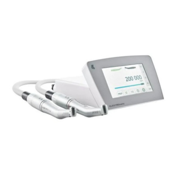
Instructions for use ELECTROmatic TM and TMM/TMC 3 Description of the product | 3.3 ELECTROmatic – Versions 3.3 ELECTROmatic – Versions ELECTROmatic TM ELECTROmatic TMM/TMC ELECTROmatic Front and rear of the device ① Control panel ⑤ Motor hose connector: - On the right, as seen from behind, label on underside of the device showing "M1"... -
Page 22: Motor Tubing
Instructions for use ELECTROmatic TM and TMM/TMC 3 Description of the product | 3.4 Motor tubing 3.4 Motor tubing KL motor hose/COMFORTbase ① Connection ELECTROmatic ④ Connection for motor ② KL motor hose 1750/2200 / ⑤ Connection for COMFORTdrive COMFORTbase 1750/2200 ③... - Page 23 Instructions for use ELECTROmatic TM and TMM/TMC 3 Description of the product | 3.5 Control panel Control element Name/type of control Feature element Toggle switch ▶ Press the control ele- "ENDO"/"PREP" modes ment, "ENDO"/"PREP" mode, to toggle between PREP and ENDO mode.
- Page 24 Instructions for use ELECTROmatic TM and TMM/TMC 3 Description of the product | 3.5 Control panel Display information examples in Preparation mode Display information example 1: PREP mode Pos. Description active/deactivated Presentation ① Motor M1, counter- active blue background clockwise...
- Page 25 Instructions for use ELECTROmatic TM and TMM/TMC 3 Description of the product | 3.5 Control panel Display information example 2: PREP mode with COMFORTdrive (TMC only) Pos. Description active/deactivated Presentation Motor M1, anticlock- deactivated grey background ① wise Motor M2, clockwise...
- Page 26 Instructions for use ELECTROmatic TM and TMM/TMC 3 Description of the product | 3.5 Control panel Display information example in ENDO mode Display information example 3: ENDO mode Pos. Description active/deactivated Presentation ① Display/toggle switch Torque is deactivated grey background "Speed"/"Torque"*...
-
Page 27: Technical Specifications Of The Electromatic
Instructions for use ELECTROmatic TM and TMM/TMC 3 Description of the product | 3.6 Technical specifications of the ELECTROmatic Pos. Description active/deactivated Presentation ⑫ Speed/torque are in- active consistent with the data from the file data- base ⑬ Selection list "Files" E0... - Page 28 Instructions for use ELECTROmatic TM and TMM/TMC 3 Description of the product | 3.6 Technical specifications of the ELECTROmatic Transportation and storage conditions Permissible ambient temperature C to +50 C / -4 F to +122 range Permissible up to a maximum hu-...
-
Page 29: Symbols On Product And Rating Plate
Instructions for use ELECTROmatic TM and TMM/TMC 3 Description of the product | 3.7 Symbols on product and rating plate pressure measured at the motor coupling using a pressure gauge Mat. no. 1.003.1050. Speed Speed range of the Motor KL 703... - Page 30 Instructions for use ELECTROmatic TM and TMM/TMC 3 Description of the product | 3.7 Symbols on product and rating plate VDE mark MET mark GOST R certification EAC conformity mark (Eurasian Conformity = Eurasische Konformität) Product characteristics Manufacturer Type Device type...
-
Page 31: Power Supply Type 4882
Instructions for use ELECTROmatic TM and TMM/TMC 3 Description of the product | 3.8 Power supply type 4882 3.8 Power supply type 4882 ① Mains connection ③ Connection cable ② Standby LED display 3.9 Technical specification for the power supply type... -
Page 32: Symbols On The Nameplate Of The Type 4882 Power Supply
Instructions for use ELECTROmatic TM and TMM/TMC 3 Description of the product | 3.10 Symbols on the nameplate of the type 4882 power supply Requirements Class of protection Protection class IP 40 Ambient conditions Permissible installation sites Indoor use Permissible ambient temperature... - Page 33 Instructions for use ELECTROmatic TM and TMM/TMC 3 Description of the product | 3.10 Symbols on the nameplate of the type 4882 power supply Manufacturing date WEEK Do not dispose of with household waste 33 / 90...
-
Page 34: Installation
Instructions for use ELECTROmatic TM and TMM/TMC 4 Installation | 4.1 Location 4 Installation 4.1 Location WARNING Installation of the device on a dental treatment unit. Electrical shock or fire hazard. ▶ Mind the electrical cord of the power supply! Route all cords appropriately such that they do not get squashed, clamped or have a chair rolling over them. - Page 35 Instructions for use ELECTROmatic TM and TMM/TMC 4 Installation | 4.2 Installation positions ▪ Installation position 4: Mount control panel as remote control Below a holder with insert On the side of a holder On a holder holder Install control panel on...
-
Page 36: Prepare Installation
Instructions for use ELECTROmatic TM and TMM/TMC 4 Installation | 4.3 Prepare installation 4.3 Prepare installation Insert holder Mounting plate ELECTROmatic installation set (Mat. no. 1.012.1883) Mounting bracket Cover panel ▶ Keep the installation set handy. ▶ For the parts from the scope of delivery required for each installation, see list in the respective installation chapter. - Page 37 Instructions for use ELECTROmatic TM and TMM/TMC 4 Installation | 4.4 Installation position 1: Mount below a holder CAUTION Damage to the dentist element. Installations involving an intervention on the treatment unit might damage components, which can interfere with the safe function and cause injury.
-
Page 38: Installation Position 2: Mount On The Side Of A Holder
Instructions for use ELECTROmatic TM and TMM/TMC 4 Installation | 4.5 Installation position 2: Mount on the side of a holder Assembly variant c) The following parts from the scope of delivery and the installation set are needed: ▪ 1x Insert holder ▪... - Page 39 Instructions for use ELECTROmatic TM and TMM/TMC 4 Installation | 4.5 Installation position 2: Mount on the side of a holder ▪ 4x Washers ② ▪ 2x Plastic screws ⑥ for fastening to the mounting plate ▶ Shorten the mounting plate with a suitable tool, if needed.
-
Page 40: Installation Position 3: Mount On A Holder Or On The Backside Of A Holder
Instructions for use ELECTROmatic TM and TMM/TMC 4 Installation | 4.6 Installation position 3: Mount on a holder or on the backside of a holder 4.6 Installation position 3: Mount on a holder or on the backside of a holder... - Page 41 Instructions for use ELECTROmatic TM and TMM/TMC 4 Installation | 4.6 Installation position 3: Mount on a holder or on the backside of a holder Assembly variant b) The following parts from the scope of delivery and the installation set are needed: ▪...
-
Page 42: Installation Position 4: Mount Control Panel As Remote Control
Instructions for use ELECTROmatic TM and TMM/TMC 4 Installation | 4.7 Installation position 4: Mount control panel as remote control 4.7 Installation position 4: Mount control panel as remote control 4.7.1 Disconnect the control panel from the control unit and install it on the mounting bracket ▶... - Page 43 Instructions for use ELECTROmatic TM and TMM/TMC 4 Installation | 4.7 Installation position 4: Mount control panel as remote control ▶ If required, break out the cable feed-through on the control panel. ▶ Guide the connecting cable of the control unit to the control panel through this opening.
-
Page 44: Mount Control Panel On A Holder / On The Backside Of A Holder
Instructions for use ELECTROmatic TM and TMM/TMC 4 Installation | 4.7 Installation position 4: Mount control panel as remote control 4.7.2 Mount control panel on a holder / on the backside of a holder CAUTION Damage to the dentist element. -
Page 45: Mount Control Panel On The Side Of A Holder
Instructions for use ELECTROmatic TM and TMM/TMC 4 Installation | 4.7 Installation position 4: Mount control panel as remote control ▶ Mount the control unit. See also: 2 4.4 Install below the dentist element, a holder or a cabinet, Page 36 4.7.3 Mount control panel on the side of a holder... - Page 46 Instructions for use ELECTROmatic TM and TMM/TMC 4 Installation | 4.7 Installation position 4: Mount control panel as remote control ▶ Mark the fixing points and drill the holes on the holder. ▶ Screw the mounting bracket with control panel to the round side of the mounting plate using the plastic screws ⑥...
-
Page 47: Mount Control Panel To Cabinet/Wall
Instructions for use ELECTROmatic TM and TMM/TMC 4 Installation | 4.7 Installation position 4: Mount control panel as remote control ▶ Mark the fixing points on the holder and drill the holes. ▶ Use the 2 screws ④ and the washers ② to screw the mounting bracket with control panel to the holder and secure it with the nuts ①. -
Page 48: Connecting The Electromatic
Instructions for use ELECTROmatic TM and TMM/TMC 4 Installation | 4.8 Connecting the ELECTROmatic CAUTION Damage to the dentist element. Installations involving an intervention on the treatment unit might damage components, which can interfere with the safe function and cause injury. -
Page 49: Startup
Instructions for use ELECTROmatic TM and TMM/TMC 5 Startup | 5.1 Connector 5 Startup Note The ELECTROmatic may be operated exclusively with the INTRA LUX KL703 LED motor (Mat. no. 1.007.0150), the COMFORTdrive motorised contra-angle handpiece and the type 4882 power supply. -
Page 50: Connecting The Motor
Instructions for use ELECTROmatic TM and TMM/TMC 5 Startup | 5.1 Connector Note The ELECTROmatic has an automatic spray air and spray water shut-off. The automatic spray air and spray water shut-off prevents the following: - Dripping of spray water after the motor is stopped... -
Page 51: Connect The Power Supply
Instructions for use ELECTROmatic TM and TMM/TMC 5 Startup | 5.1 Connector ELECTROmatic TM ELECTROmatic TMM/TMC ▶ Set the spray regulation on the hose to maximum amount of water. See also: 2 6.3 Regulating the spray water, Page 56 5.1.5 Connect the power supply CAUTION Power supply and cords/hoses are on the floor. -
Page 52: Calibrate The Foot Control
Instructions for use ELECTROmatic TM and TMM/TMC 5 Startup | 5.2 Calibrate the foot control ▶ Affix the cord with cord ties and/or cord tape. 5.2 Calibrate the foot control ▶ Press the foot control down once as far as it will go (maximal pressure) in order to calibrate the foot control. -
Page 53: Making The Device Settings
Instructions for use ELECTROmatic TM and TMM/TMC 5 Startup | 5.4 Making the device settings ▶ Place the airflow measuring tube ① (Mat. no. 0.411.4441) on the motor. ▶ Press the foot control to start the motor. ▶ Adapt the system pressure of the treatment centre appropriately such that the cooling airflow is 6 to 9 Nl/min (upper edge of sphere ②). - Page 54 Instructions for use ELECTROmatic TM and TMM/TMC 5 Startup | 5.4 Making the device settings Display information Setting You can select from 3 different kinds of key tones upon touching a control element. The volume of the tone when you touch a control element can be adjusted between 1 and 3.
-
Page 55: Operation
Instructions for use ELECTROmatic TM and TMM/TMC 6 Operation | 6.1 Switching the ELECTROmatic on/off 6 Operation CAUTION Germ formation. Infections. ▶ Before treating a patient, let the spray air and spray water exit for at least 20 seconds. ▶ Before the first start-up and after downtimes (weekends, holidays, vaca- tions, etc.), the air and water lines must be purged and/or rinsed. -
Page 56: Starting-Up The Motor
Instructions for use ELECTROmatic TM and TMM/TMC 6 Operation | 6.2 Starting-up the motor ▶ To switch the device off, unplug the unit from the mains. Note The power consumption on idling is so low that the device does not need to be disconnected. -
Page 57: Prep Mode
Instructions for use ELECTROmatic TM and TMM/TMC 6 Operation | 6.4 PREP mode 6.4 PREP mode Operation general If the display shows the "PREP" control element, preparation mode is active. Activated values are shown with a blue background and can be changed. -
Page 58: Changing The Direction Of Rotation
Instructions for use ELECTROmatic TM and TMM/TMC 6 Operation | 6.4 PREP mode ð The set value is being saved. Requirement Two motors are connected. ▶ Press the control element, "Transmission ratio". ð The display shows a selection list. ▶ Select the transmission ratio from the selection list. Scroll the selection list up or down and select the transmission ratio. -
Page 59: Protection Function Safedrive
WARNING Use of incorrect straight and contra-angle handpieces. Risk of burn injury or overheating. ▶ Use only original KaVo high-speed handpieces of the 25L, E25, M25, M05, 25LP, 25LPA, 25LPR, 25LCA series or the COMFORTdrive motorised contra- angle handpiece. WARNING Inactivation of the SAFEdrive function. - Page 60 In all activated speed memories, the SAFEdrive icon is shown with a blue background. Use with the SAFEdrive function With regard to handpieces from third-party manufacturers, KaVo recommends inactivating the SAFEdrive function as the SAFEdrive protection function is ef- fective only with high-speed handpieces from KaVo.
-
Page 61: Endo Mode
The INTRA LUX KL 703 LED motor has a maximum torque range from 0.15 to 3 Ncm. If the torque is in excess of 2.0 Ncm, KaVo recommends using a reducing contra-angle handpiece 3:1 or 8:1 in order to reduce the load on and heating of the motor. -
Page 62: Using The Endo Mode
▶ Once the value is activated, use the slider to set the value. 6.5.2 File database ELECTROmatic TM and TMM/TMC possess an integrated file database. It is ne- cessary to check if the file data are up-to-date by comparing them to the re- spective manufacturer information. -
Page 63: Defining/Changing Endo File Sequences In The File Editor
Instructions for use ELECTROmatic TM and TMM/TMC 6 Operation | 6.5 ENDO Mode Manufacturer File system Manufacturer File system COLTENE ▪ HyFlex™ EDM Dentsply ▪ ProFile® ▪ HyFlex™ CM ▪ ProTaper® Universal ▪ BioRace ▪ ProTaper Next KOMET ▪ F360 ▪... - Page 64 Instructions for use ELECTROmatic TM and TMM/TMC 6 Operation | 6.5 ENDO Mode ð The display shows a keyboard. ▶ Edit "SEQUENCE 1" with the keyboard and confirm the input made with the "Checkmark" control element. ▶ Tap the second column "File system" and shift the column vertically in order to select the file system (presently: ProFile).
- Page 65 Instructions for use ELECTROmatic TM and TMM/TMC 6 Operation | 6.5 ENDO Mode ▶ Activate the "File Editor Sorting" setting of the device, if applicable. See also: 2 5.4 Making the device settings, Page 53 ▶ Tap the first column "File position" and shift the column vertically in order to shift the position of the selected file in the sequence (presently: E1).
- Page 66 Instructions for use ELECTROmatic TM and TMM/TMC 6 Operation | 6.5 ENDO Mode ð The display shows file sequence "SEQUENCE 1" in editing mode. ▶ In order to define user-defined files, tap the second column "File system" and shift the column vertically until "FILE" is shown with a blue background.
- Page 67 Instructions for use ELECTROmatic TM and TMM/TMC 6 Operation | 6.5 ENDO Mode ▶ Open the file editor, then tap file sequence "SEQUENCE 1" to display the se- lection list of the file sequences. ▶ Tap the "Pen" control element to edit the sequence.
- Page 68 Instructions for use ELECTROmatic TM and TMM/TMC 6 Operation | 6.5 ENDO Mode Deactivating file from file sequence If the user does not need all 10 files of the file sequence for treatment, he or she can deactivate files in the sequence.
-
Page 69: Selecting An Endo File Sequence
Instructions for use ELECTROmatic TM and TMM/TMC 6 Operation | 6.5 ENDO Mode 6.5.4 Selecting an ENDO file sequence ▶ Select ENDO file sequences using the "File sequence" selection list by press- ing the desired file sequence (presently SEQUENCE 1). -
Page 70: Setting The Endo Torque
Instructions for use ELECTROmatic TM and TMM/TMC 6 Operation | 6.5 ENDO Mode If the set speed differs from the recommended value of this file, a crossed-out factory symbol is shown. See also: 2 6.5.2 File database, Page 62 6.5.7 Setting the ENDO torque... - Page 71 Instructions for use ELECTROmatic TM and TMM/TMC 6 Operation | 6.5 ENDO Mode ▶ Select the torque mode from the selection list. ð The torque mode is shown on the display. ð The displayed torque mode is saved. Torque Control function Torque Control is active.
- Page 72 Instructions for use ELECTROmatic TM and TMM/TMC 6 Operation | 6.5 ENDO Mode Autorev / Forward function Autorev / Forward is active. ▶ Press the foot pedal. ð The motor starts. Once 90% of the set torque value are reached, a notifying beep is issued and the light starts to pulse.
-
Page 73: Decommissioning
Instructions for use ELECTROmatic TM and TMM/TMC 7 Decommissioning | 7.1 Disconnecting the electrical connection 7 Decommissioning 7.1 Disconnecting the electrical connection ▶ To disconnect the power cable from the mains, unplug the connector of the power supply from the supply mains socket. -
Page 74: Reprocessing Steps In Accordance With Din En Iso 17664
Instructions for use ELECTROmatic TM and TMM/TMC 8 Reprocessing steps in accordance with DIN EN ISO 17664 | 8.1 Cleaning 8 Reprocessing steps in accordance with DIN EN ISO 17664 Note The reprocessing steps for the motor, the COMFORTdrive and the straight and contra-angle handpieces are described in the corresponding instructions for use. -
Page 75: Automated External And Internal Cleaning
▶ The germ reduction of the ELECTROmatic must be carried out via the dental unit. KaVo recommends the following products for germ reduction of the spray water of the dental unit: ▪ KaVo Oxygenal 6 made by KaVo Dental GmbH www.kavo.com ▪... -
Page 76: Automated External And Internal Disinfection
Instructions for use ELECTROmatic TM and TMM/TMC 8 Reprocessing steps in accordance with DIN EN ISO 17664 | 8.3 Packaging ▶ Connect the ELECTROmatic to the dental unit. ▶ Follow the instructions for germ reduction of the dental unit. The product should be used according to the instructions of the manufacturer and the Instructions for Use of the dental unit. -
Page 77: Servicing
Note KaVo grants no guarantee of function and KaVo accepts no liability unless ori- ginal replacement parts and operating materials are used exclusively. Note The device must not be serviced or repaired during operation/use. -
Page 78: Replacing The Led Lamp Of The Kl 703 Motor
▶ Do not touch lamp after previous operation. Let the lamp cool off. ▶ Pull the sleeve off while twisting it slightly. ▶ Push the old KaVo Mini LED lamp out of the mount with your fingernail and remove it. -
Page 79: Replacing The Led Lamp Of The Comfortbase
▪ Case 1: KaVo MULTI LED lamp is on. ▪ Case 2: KaVo MULTI LED lamp is red or off. - Take the KaVo MULTI LED lamp out of its socket as described above and re-insert it after rotating it 180° about its axis. - Page 80 Instructions for use ELECTROmatic TM and TMM/TMC 9 Servicing | 9.4 Replacing the motor hose ▶ Dispose of the defective motor cord in appropriate manner. 80 / 90...
-
Page 81: 10Troubleshooting
Instructions for use ELECTROmatic TM and TMM/TMC 10 Troubleshooting 10 Troubleshooting Note This product displays error messages and/or instructions optically on its dis- play. The motor is shut off in any case of malfunction. ▶ If the error message does not disappear or the error is reported again, con- tact Service. - Page 82 Also refer to: Chapter speed handpiece from KaVo. SAFEdrive alert. on Protection Function ▶ If you use a high-speed handpiece from KaVo, SAFEdrive relieve the handpiece of its load for at least 2 seconds, i.e. lift it off the tooth.
- Page 83 Instructions for use ELECTROmatic TM and TMM/TMC 10 Troubleshooting Malfunction Cause Remedy ▶ Confirm message and check or correct the pro- Event E8 Saved data or settings gram settings. have been reset to ▶ If error persists, notify the service engineer.
-
Page 84: 11Accessories And Consumables
Instructions for use ELECTROmatic TM and TMM/TMC 11 Accessories and consumables 11 Accessories and consumables Name Material number Filter insert 1.007.9736 Airflow measuring tube 0.411.4441 Adaptor for the airflow measuring tube 1.005.1702 Motor INTRA LUX KL 703 LED 1.007.0150 KL Motor hose 1750 1.011.7200... -
Page 85: 12Information About Electromagnetic Compatibility
Instructions for use ELECTROmatic TM and TMM/TMC 12 Information about electromagnetic compatibility | 12.1 Guidelines and manufacturer's declaration - electromag- netic emission 12 Information about electromagnetic compatibility 12.1 Guidelines and manufacturer's declaration - electromagnetic emission The ELECTROmatic is intended for use in an environment of the kind specified below. -
Page 86: Guidelines And Manufacturer's Statement - Electromagnetic Immunity
Instructions for use ELECTROmatic TM and TMM/TMC 12 Information about electromagnetic compatibility | 12.3 Guidelines and manufacturer's statement - Electromag- netic immunity Interference im- IEC 60601 test Compliance level Electromagnetic environment munity tests levels - Guidelines Electrostatic discharge ± 8 kV contact dis- ±... - Page 87 Instructions for use ELECTROmatic TM and TMM/TMC 12 Information about electromagnetic compatibility | 12.3 Guidelines and manufacturer's statement - Electromag- netic immunity Interference im- IEC 60601 test Compliance level Electromagnetic environment munity tests levels - Guidelines Wire-based HF inter- Handheld and mobile wireless...
-
Page 88: Recommended Safe Distances Between Portable And Mobile Hf Telecommunications Equipment And The Electromatic
Instructions for use ELECTROmatic TM and TMM/TMC 12 Information about electromagnetic compatibility | 12.4 Recommended safe distances between portable and mo- bile HF telecommunications equipment and the ELECTROmatic Note 2: These guidelines may not be applicable in every case. The propagation of electromagnetic waves is subject to absorption and reflection by buildings, objects, and people.
Need help?
Do you have a question about the ELECTROmatic TM and is the answer not in the manual?
Questions and answers