
Related Manuals for Moxa Technologies UC-1200A Series


Summary of Contents for Moxa Technologies UC-1200A Series
- Page 1 UC-1200A Series Hardware User Manual Version 1.0, November 2023 www.moxa.com/products © 2023 Moxa Inc. All rights reserved.
- Page 2 UC-1200A Series Hardware User Manual The software described in this manual is furnished under a license agreement and may be used only in accordance with the terms of that agreement. Copyright Notice © 2023 Moxa Inc. All rights reserved. Trademarks The MOXA logo is a registered trademark of Moxa Inc.
-
Page 3: Table Of Contents
Table of Contents Introduction ............................4 Package Checklist ..........................4 Product Features ........................... 4 Product Specifications ..........................4 Hardware Introduction ......................... 5 Appearance ............................5 Dimensions ............................7 LED Indicators ............................8 Reset Button ............................8 Reset to Default ............................ 8 Real-time Clock ............................. -
Page 4: Introduction
Rich programmable LEDs and a programmable button for easy installation and maintenance -40 to 60°C operating temperature range • Long-term Linux support until 2031; includes bug fixes and security patches • Product Specifications NOTE The latest specifications for Moxa's products can be found at https://www.moxa.com. UC-1200A Series Hardware User Manual... -
Page 5: Hardware Introduction
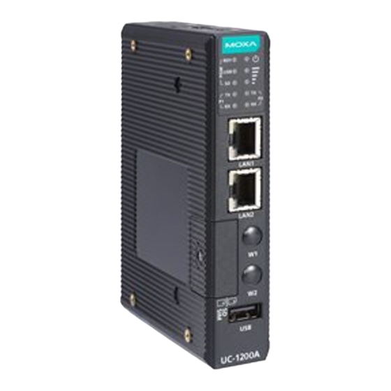
In this chapter, we provide basic information about the embedded computer’s hardware and its various components. Appearance Front View UC-1200A Series Hardware User Manual... - Page 6 Top View Bottom View UC-1200A Series Hardware User Manual...
-
Page 7: Dimensions
Dimensions UC-1200A Series Hardware User Manual... -
Page 8: Led Indicators
There is a risk of explosion if the battery is replaced with an incorrect type. Replace only with the same or equivalent type recommended by the manufacturer. Dispose of used batteries according to the manufacturer’s instructions. UC-1200A Series Hardware User Manual... -
Page 9: Installation Options
Use four screws (M3 x 4 mm) to fasten the wall- Use another four screws (M3 x 6 mm) to mount the mounting brackets on the left panel of the computer on a wall or a cabinet. computer. UC-1200A Series Hardware User Manual... -
Page 10: Placing The Round Stickers On The Screws
The ideal environment to store the stickers is at 22°C (72°F) and less than 50% relative humidity. • Keep the extra two stickers in a safe place so that only authorized persons can access them. • UC-1200A Series Hardware User Manual... -
Page 11: Hardware Connection Description
Terminal Block Connect the 12 to 24 VDC power line to the terminal block, which is connector to the UC-1200A Series computer. If the power is supplied properly, the “Power” LED will glow a solid green light. The power input location and pin definition are shown in the adjacent diagram. -
Page 12: Connecting To The Network
The UC-1200A computers come with a USB port located on the lower part of the front panel for connecting to a device with a USB interface. The USB port uses a type A connector. By default, the USB storage connected to this interface is mounted at /mnt/usbstorage. UC-1200A Series Hardware User Manual... -
Page 13: Inserting The Micro Sd Card And Sim Card
The console port is an RS-232 port that can be connected to a 4-pin pin header cable. You can use this port for debugging or firmware upgrade. Signal Connecting the Antennas The UC-1200A provides a Mini PCIe socket for installing a wireless module. User can purchase "A-CRF-SMIF-100" which is an SMA connector accessory package. UC-1200A Series Hardware User Manual... -
Page 14: Regulatory Approval Statements
(Les antennes sont à plus de 20 cm du corps d'une personne). WARNING This is a class A product. In a domestic environment this product may cause radio interference in which case the user may be required to take adequate measures. UC-1200A Series Hardware User Manual...
Need help?
Do you have a question about the UC-1200A Series and is the answer not in the manual?
Questions and answers