Advertisement
Quick Links
Quick Installation Guide
Moxa Americas:
Toll-free: 1-888-669-2872
Tel:
1-714-528-6777
Fax:
1-714-528-6778
Moxa Europe:
Tel:
+49-89-3 70 03 99-0
Fax:
+49-89-3 70 03 99-99
Moxa India:
Tel:
+91-80-4172-9088
Fax:
+91-80-4132-1045
UC-8112-ME-T
Edition 1.0, June 2016
Technical Support Contact Information
www.moxa.com/support
2016 Moxa Inc. All rights reserved.
Moxa China (Shanghai office):
Toll-free: 800-820-5036
Tel:
+86-21-5258-9955
Fax:
+86-21-5258-5505
Moxa Asia-Pacific:
Tel:
+886-2-8919-1230
Fax:
+886-2-8919-1231
P/N: 1802081120010
*1802081120010*
Advertisement

Related Manuals for Moxa Technologies UC-8112-ME-T


Summary of Contents for Moxa Technologies UC-8112-ME-T
- Page 1 UC-8112-ME-T Quick Installation Guide Edition 1.0, June 2016 Technical Support Contact Information www.moxa.com/support Moxa Americas: Moxa China (Shanghai office): Toll-free: 1-888-669-2872 Toll-free: 800-820-5036 Tel: 1-714-528-6777 Tel: +86-21-5258-9955 Fax: 1-714-528-6778 Fax: +86-21-5258-5505 Moxa Europe: Moxa Asia-Pacific: Tel: +49-89-3 70 03 99-0...
-
Page 2: Package Checklist
Mini PCIe socket to support cellular modules. These versatile communication capabilities let users efficiently adapt the UC-8112-ME-T to a variety of complex communications solutions. Package Checklist Before installing the UC-8112-ME-T, verify that the package contains the following items: • UC-8112-ME-T embedded computer (with SD card) •... - Page 3 Bottom Panel View Front Panel View LED Indicators LED Name Color Function Steady On USB device is connected and Green working normally. USB device is not connected. Steady On SD Card inserted and working normally. Green SD card is not detected. Power is on and the computer is working Green normally.
- Page 4 DIN-Rail Mounting Attach the DIN-rail mounting kit on the rear panel of the UC-8112-ME-T as shown in the following illustration. Make sure that the two screws are securely fastened. Pull down the bottom slider of the DIN-rail bracket located at...
-
Page 5: Connector Description
Connector Description Power Connector Connect the power jack (in the package) to the UC-8112-ME-T’s DC terminal block (located on the top panel), and then connect the power adapter. It takes about 30 seconds for the system to boot up. Once the system is ready, the Power LED will light up. - Page 6 There is a risk of explosion if the battery is replaced with an incorrect type of battery. Cellular Module The UC-8112-ME-T comes with a built-in PCIe socket for wireless communication. To install a cellular module, do the following: 1. Remove the two screws on the 2.
- Page 7 3. Remove the four screws on the 4. Remove the screw on the silver cover on the right panel and metal cover. remove the cover. 5. Remove the three screws on 6. Remove the two screws on the top panel. the bottom panel.
- Page 8 8. Remove the metal cover of the computer and locate the cellular module socket. 9. Remove the screw next to the socket and replace it with the bronze screw (in the package) as shown below: 10. Attach one thermal pad to the cellular module cover and the other thermal pad to the module pad.
- Page 9 11. Attach the cellular module to the module pad. 12. Mount the module cover on the cellular module and use screws on both sides to secure the cover. 13. Insert the module into the socket and secure it using a screw from the package.
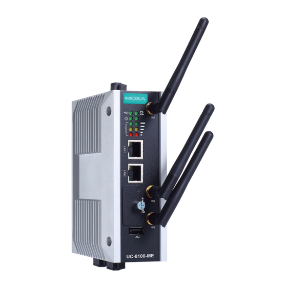
- Page 10 14. Connect antenna cables to the cellular module. There are three antenna connectors on the cellular module: W1 and W3 are for cellular antennas and W2 is for GPS antenna. 15. Insert the antenna connectors through the antenna cable holes on the front panel of the cover as shown below: 16.
- Page 11 19. Replace the cover of the computer and fasten the screws to secure the cover. Accessing the UC-8112-ME-T Using a PC You can use a PC to access the UC-8112-ME-T by one of the following methods: A. Through the serial console port with the following settings:...
- Page 12 B. Using SSH over the network. Refer to the following IP addresses and login information: Default IP Address Netmask LAN 1 192.168.3.127 255.255.255.0 LAN 2 192.168.4.127 255.255.255.0 Login: moxa Password: moxa - 12 -...
Need help?
Do you have a question about the UC-8112-ME-T and is the answer not in the manual?
Questions and answers