
Related Manuals for Moxa Technologies UC-7101


Summary of Contents for Moxa Technologies UC-7101
- Page 1 UC-7101 Hardware User’s Manual Second Edition, June 2008 www.moxa.com/product © 2008 Moxa Inc., all rights reserved. Reproduction without permission is prohibited.
-
Page 2: Copyright Notice
UC-7101 Hardware User’s Manual The software described in this manual is furnished under a license agreement and may be used only in accordance with the terms of that agreement. Copyright Notice Copyright © 2008 Moxa Inc. All rights reserved. Reproduction without permission is prohibited. -
Page 3: Table Of Contents
Chapter 3 Hardware Connection Description .............3-1 Wiring Requirements ....................... 3-2 Connecting the Power....................3-2 Grounding the UC-7101 Embedded Computer ............3-2 Connecting Data Transmission Cables ..................3-3 Connecting to the Network................... 3-3 Connecting to a Serial Device ..................3-4 Serial Console Port ....................... 3-4... -
Page 4: Chapter 1 Introduction
10/100 Mbps Ethernet ports, RS-232/422/485 serial ports, and an ARM9 processor. The computers come with Linux pre-installed. In addition, the UC-7101 has an internal SD socket for storage expansion to offer high performance communication with unlimited storage in a super-compact, palm-size box. -
Page 5: Overview
The UC-7101 comes with the µClinux operating system pre-installed. Software written for desktop PCs is easily ported to the UC-7101 computers with a GNU cross complier, so that you will not need to spend time modifying existing software code. The operating system, device drivers, and your own software can all be stored in the computers’... -
Page 6: Product Features
UC-7101 Hardware User’s Manual Introduction Product Features The UC-7101 series computers have the following features: Moxa ART ARM9 32-bit 192 MHz processor 16 MB RAM (about 12 MB of user programmable space) 8 MB Flash ROM (about 4 MB of user programmable space) -
Page 7: Software Specifications-Uc-7101 (Μclinux)
UC-7101 Hardware User’s Manual Introduction Power Requirements Power Input 12 to 48 VDC Power Consumption 300 mA @ 12 VDC (UC-7101) Mechanical Dimensions (W D H) 67 100.4 22 mm (UC-7101) Weight 130 g Construction Material aluminum, 1 mm Mounting... -
Page 8: Hardware Block Diagrams
UC-7101 Hardware User’s Manual Introduction Hardware Block Diagrams UC-7101 Ethernet Power 16 MB Circuit SDRAM 8 MB MOXA ART CPU Flash 32-bit ARM9 192 MHz Watchdog UART UART Serial Console Port Port RS-232/422/485 RS-232... -
Page 9: Chapter 2 Hardware Introduction
Hardware Introduction Chapter 2 The UC-7101 is compact, rugged embedded computers designed for industrial applications. The LED indicators on the computers’ outer casing help you monitor the performance of the computers, and assist in identifying trouble spots. The hardware platform is both reliable and stable, and allows you to devote the bulk of your attention to developing your own application. -
Page 10: Appearance
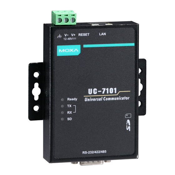
UC-7101 Hardware User’s Manual Hardware Introduction Appearance UC-7101 Ethernet (10/100BaseTx) 12 to 48 VDC RS-232 Console Terminal Internal SD Slot for Storage Expansion (remove cover to access) Serial Port (RS-232/422/485) -
Page 11: Dimensions
UC-7101 Hardware User’s Manual Hardware Introduction Dimensions UC-7101 unit = mm (inch) 6 (0.24) 4 (0.16) 12.5 (0.49) 25 (0.98) 21.3 7 (0.28) (0.8) 43.3 (1.67) 22 (0.87) 67 (2.64) 78 (3.07) 90 (3.54) -
Page 12: Panel Views
UC-7101 Hardware User’s Manual Hardware Introduction Panel Views UC-7101 Top View Reset Button Terminal Block Power Input RJ45 10/100 Mbps Ethernet Ports Nameplate View DIN-Rail screw hole Wallmount screw hole Bottom View DB9 (male) Serial Port... -
Page 13: Led Indicators
To install an SD card, first remove the outer cover of the embedded computer to access the SD slot. The internal SD slot is located on the top side of UC-7101 main board, in the slot on the right side of the UC-7101, but lower than the cover screw. -
Page 14: Real Time Clock
Real Time Clock The real time clock in the UC-7101 embedded computers is powered by a lithium battery. We strongly recommend that you get help from Moxa’s technical support team to replace the lithium battery. -
Page 15: Hardware Connection Description
Hardware Connection Description Chapter 3 In this chapter, we show how to connect the UC-7101 embedded computer to the network and to various devices. In this chapter, we cover the following topics: Wiring Requirements Connecting the Power Grounding the UC-71... -
Page 16: Wiring Requirements
Connecting the Power Connect the “live-wire” end of the 12-48 VDC power adaptor to the UC-7101 terminal block. If the power is supplied properly, the “Ready” LED will glow a solid green color after a 25 to 30 second delay. -
Page 17: Connecting Data Transmission Cables
12-48V Connecting Data Transmission Cables This section describes how to connect the UC-7101 to the network, to serial devices, and to a serial COM terminal. Connecting to the Network Connect one end of the Ethernet cable to the UC-7101’s 10/100M Ethernet port, and the other end of the cable to the Ethernet network. -
Page 18: Connecting To A Serial Device
UC-7101 The SD slot is located on the right side of the UC-7101 enclosure. To install an SD card, you must first remove the protective cover to access the slot, and then plug the SD card directly into the slot. - Page 19 UC-7101 Hardware User’s Manual Hardware Connection Description Step 2: After removing the cover, insert the SD memory card into the slot. NOTE: To remove the SD card from the slot, press the SD card in slightly forward with your finger, and then remove your finger to cause the card to spring out partially. You may now grasp...
Need help?
Do you have a question about the UC-7101 and is the answer not in the manual?
Questions and answers