Moxa Technologies UC-8200 Series Quick Installation Manual
Hide thumbs
Also See for UC-8200 Series:
- Hardware user manual (23 pages) ,
- Hardware user manual (22 pages)
Table of Contents
Advertisement
Quick Links
Quick Installation Guide
Moxa Americas:
Toll-free: 1-888-669-2872
Tel:
1-714-528-6777
Fax:
1-714-528-6778
Moxa Europe:
Tel:
+49-89-3 70 03 99-0
Fax:
+49-89-3 70 03 99-99
Moxa India:
Tel:
+91-80-4172-9088
Fax:
+91-80-4132-1045
UC-8200 Series
Version 1.0, July 2019
Technical Support Contact Information
www.moxa.com/support
2019 Moxa Inc. All rights reserved.
Moxa China (Shanghai office):
Toll-free: 800-820-5036
Tel:
+86-21-5258-9955
Fax:
+86-21-5258-5505
Moxa Asia-Pacific:
Tel:
+886-2-8919-1230
Fax:
+886-2-8919-1231
P/N: 1802082000010
*1802082000010*
Advertisement
Table of Contents

Related Manuals for Moxa Technologies UC-8200 Series


Summary of Contents for Moxa Technologies UC-8200 Series
- Page 1 UC-8200 Series Quick Installation Guide Version 1.0, July 2019 Technical Support Contact Information www.moxa.com/support Moxa Americas: Moxa China (Shanghai office): Toll-free: 1-888-669-2872 Toll-free: 800-820-5036 Tel: 1-714-528-6777 Tel: +86-21-5258-9955 Fax: 1-714-528-6778 Fax: +86-21-5258-5505 Moxa Europe: Moxa Asia-Pacific: Tel: +49-89-3 70 03 99-0...
-
Page 2: Package Checklist
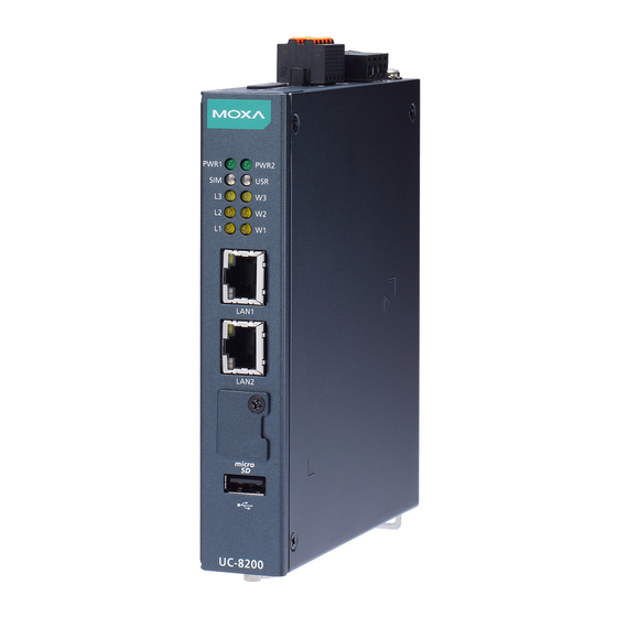
Warranty card IMPORTANT! Notify your sales representative if any of the above items are missing or damaged. UC-8200 Series Panel Layout The following figures show the panel layouts of the UC-8200 Series: UC-8210 Series Top Panel View - 2 -... - Page 3 Bottom Panel View Front Panel View - 3 -...
- Page 4 UC-8220 Series Top Panel View Bottom Panel View - 4 -...
- Page 5 Installing the UC-8200 Series DIN-rail Mounting The aluminum DIN-rail attachment plate is already attached to the product’s casing. To mount the UC-8200 Series on to a DIN rail, make sure that the stiff metal spring is facing upwards and follow these steps.
- Page 6 Push the slider back into place. Wall Mounting (optional) The UC-8200 Series can be mounted on to a wall using a wall-mounting kit. The optional wall-mounting kit should be purchased separately. Follow these steps to mount the computer on to a wall:...
-
Page 7: Connector Description
Connector Description Power Connector Connect the power jack (in the package) to the UC-8200 Series’ DC terminal block (located on the top panel), and then connect the power adapter. It takes about 30 seconds for the system to boot up. - Page 8 – microSD Card Sockets The UC-8200 Series comes with a micro SD socket for storage expansion. The microSD socket is located at the lower part on the front panel. To install the card, remove the screw and the protection cover to access the socket, and then insert the microSD card into the socket directly.
-
Page 9: Pin Definition
SIM card. Real-time Clock The real-time clock in the UC-8200 Series is powered by a lithium battery. We strongly recommend that you do not replace the lithium battery without the help of a Moxa support engineer. If you need to change the battery, contact the Moxa RMA service team. -
Page 10: Installing The Cellular Module
Accessing the UC-8200 Series Using a PC You can use a PC to access the UC-8200 Series by one of the following methods: A. Through the serial console port with the following settings: Baudrate=115200 bps, Parity=None, Data bits=8, Stop bits... - Page 11 4. Install the cellular module onto the socket and fasten the two screws on the module. 5. Connect the antenna cables to the antenna connectors. - 11 -...
-
Page 12: Installing The Wi-Fi Module
6. The UC-8220 Series supports two cellular antennas and a GPS antenna. Connect the cable to the correct antenna connectors. 7. When finished, place the side cover back on the computer and secure it. Installing the Wi-Fi Module The Wi-Fi module is not included in the package, you need to purchase separately. - Page 13 2. Remove the two silver 3. Install the Wi-Fi module screws on the socket. in the socket and fasten two black screws on the module. Also, fasten the two bronze screws on the board. 4. Remove the plastic protection covers on the antenna connectors. 5.
- Page 14 6. Install the heat sink pad on the module and then fasten two silver screws. 7. Replace the side cover. Connecting Antennas There are two cellular antenna There are two Wi-Fi antenna connectors (C1 and C2) on the connectors (W1 and W2) on the front panel of the UC-8220 top panel of the UC-8220 Series.
Need help?
Do you have a question about the UC-8200 Series and is the answer not in the manual?
Questions and answers