
Subscribe to Our Youtube Channel
Related Manuals for Moxa Technologies UC-3100 Series


Summary of Contents for Moxa Technologies UC-3100 Series
- Page 1 UC-3100 Series Quick Installation Guide Version 4.1, April 2021 Technical Support Contact Information www.moxa.com/support 2021 Moxa Inc. All rights reserved. P/N: 1802031000025 *1802031000025*...
-
Page 2: Package Checklist
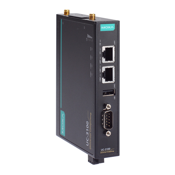
Overview Moxa UC-3100 Series computers can be used as smart edge gateways for data pre-processing and transmission, as well as for other embedded data-acquisition applications. The UC-3100 Series includes three models, UC-3101, UC-3111 and UC-3121, each supporting different wireless options and protocols. Please refer to the datasheet for more information. - Page 3 UC-3111 - 3 -...
- Page 4 UC-3121 - 4 -...
- Page 5 LED Indicators Status Function Notes Name Green Power is on Refer to the Function Button (FN Button) FN button is pressed and LED Indicators Power is off section in the hardware/software user manual for more details. Green The computer is in power (blinking) conservation mode LAN1/...
-
Page 6: Din Rail Mounting
DIN-rail Mounting To mount the UC-3100 on to a DIN rail, do the following: 1. Pull down the slider of the DIN-rail bracket located at the back of the unit 2. Insert the top of the DIN rail into the slot just below the upper hook of the DIN-rail bracket. -
Page 7: Connector Description
Connector Description Power Connector Connect the power jack (in the package) to the UC-3100’s DC terminal block (located on the bottom panel), and then connect the power adapter. It takes several seconds for the system to boot up. Once the system is ready, the SYS LED will light up. - Page 8 RS-232 RS-422 RS-485 TxD-(A) – TxD+(A) – RxD+(B) Data+(B) RxD-(A) Data-(A) – – – – – – – – – CAN Port The UC-3121 comes with a CAN port which uses the DB9 male connector and is compatible with the CAN 2.0A/B standard. The pin assignment of the port is shown below: Signal Name –...
- Page 9 Wi-Fi The UC-3111 and UC-3121 models come with a built-in Wi-Fi module. You must connect the antenna to the RP-SMA connector before you can use the Wi-Fi function. The W1 and W2 connectors are interfaces to the Wi-Fi module. Bluetooth The UC-3111 and UC-3121 models come with a built-in Bluetooth module.
- Page 10 Accessing the UC-3100 Using a PC You can use a PC to access the UC-3100 by one of the following methods: A. Through the serial console port with the following settings: Baudrate = 115200 bps, Parity = None, Data bits = 8, Stop bits = 1, Flow Control = None ATTENTION Remember to choose the “VT100”...
- Page 11 ATTENTION • This device is an open-type device that is to be installed in an enclosure only accessible with the use of a tool, suitable for the environment. • This equipment is suitable for use in Class I, Division 2, Groups A, B, C, and D or non-hazardous locations only.
- Page 12 ATEX Specifications 1. Ex nA IIC T4 Gc 2. Ambient Range:-40°C ≤ Ta ≤ +70°C, or -40°C ≤ Tamb ≤ +70°C 3. Rated Cable Temp ≧ 90 °C 4. Standards Covered: EN 60079-0:2012+A11:2013 EN 60079-15:2010 5. Hazardous Location : Class I, Division 2, Groups A, B, C, and D Special Conditions of Use: These devices shall be mounted in a suitable tool-accessible ATEX-certified enclosure that is rated at least IP54 as defined in...
Need help?
Do you have a question about the UC-3100 Series and is the answer not in the manual?
Questions and answers