Table of Contents
Advertisement
Quick Links
Quick Installation Guide
Moxa Americas:
Toll-free: 1-888-669-2872
Tel:
1-714-528-6777
Fax:
1-714-528-6778
Moxa Europe:
Tel:
+49-89-3 70 03 99-0
Fax:
+49-89-3 70 03 99-99
Moxa India:
Tel:
+91-80-4172-9088
Fax:
+91-80-4132-1045
UC-2100-W Series
Version 2.0, October 2019
Technical Support Contact Information
www.moxa.com/support
2019 Moxa Inc. All rights reserved.
Moxa China (Shanghai office):
Toll-free: 800-820-5036
Tel:
+86-21-5258-9955
Fax:
+86-21-5258-5505
Moxa Asia-Pacific:
Tel:
+886-2-8919-1230
Fax:
+886-2-8919-1231
P/N: 1802021000211
*1802021000211*
Advertisement
Table of Contents

Related Manuals for Moxa Technologies UC-2100-W Series


Summary of Contents for Moxa Technologies UC-2100-W Series
- Page 1 UC-2100-W Series Quick Installation Guide Version 2.0, October 2019 Technical Support Contact Information www.moxa.com/support Moxa Americas: Moxa China (Shanghai office): Toll-free: 1-888-669-2872 Toll-free: 800-820-5036 Tel: 1-714-528-6777 Tel: +86-21-5258-9955 Fax: 1-714-528-6778 Fax: +86-21-5258-5505 Moxa Europe: Moxa Asia-Pacific: Tel: +49-89-3 70 03 99-0...
-
Page 2: Model Names And Package Checklist
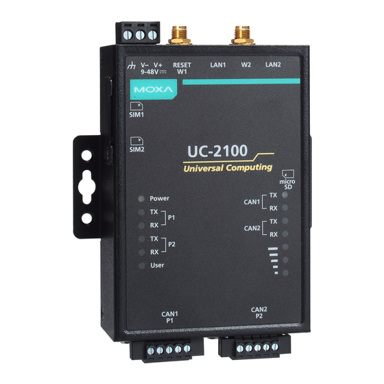
Overview The UC-2100-W Series computing platform is designed for embedded data acquisition and processing applications. The computer comes with up to two software-selectable RS-232/422/485 full-signal serial ports and single or dual Ethernet LAN ports. In addition, the Arm-based computing platform is available in various models that can fulfill diverse interface requirements, such as dual serial, LAN ports, and wireless connections. - Page 3 Appearance UC-2114 UC-2116 - 3 -...
-
Page 4: Led Indicators
CAN port is not receiving data Reset Button The UC-2100-W Series computer is provided with a reset button, which is located on the top panel of the computer. To reboot the computer, press the reset button less than 1 second. Press and hold the reset button between 7 to 9 seconds to reset the computer to the factory default settings. -
Page 5: Installing The Computer
Installing the Computer Wall or Cabinet Mounting Use two screws per side to mount the UC-2100-W Series on a wall or inside a cabinet. Wiring Requirements Be sure to read and follow these common safety precautions before proceeding with the installation of any electronic device: •... -
Page 6: Connecting The Power
CAUTION Be careful when handling the unit. When the unit is plugged in, the internal components generate heat, and consequently the outer casing may feel hot to the touch. Connecting the Power Connect the 9 to 48 VDC power line to the terminal block, which is connected to the UC- 2100-W Series computer. -
Page 7: Connecting To The Network
Serial Console Port & Pinouts Serial Console Cable Signal Connecting to the Network The Ethernet ports are located on the top or bottom panel of the UC- 2100-W computers. The pin assignments for the Ethernet port are shown in the following figure. If you are using your own cable, make sure that the pin assignments on the Ethernet cable connector match the pin assignments on the Ethernet port. -
Page 8: Installing Sim Cards
Connecting to a CAN Device The UC-2114 and UC-2116 come with two CAN ports, which use the 5- pin terminal block and are compatible with the CAN 2.0A/B standard. The pin assignment of the port is shown below. Signal Chassis Vout Installing SIM Cards You will need to install a SIM card on your UC-2100-W computer. -
Page 9: Real-Time Clock
1. Remove the screws on the DIP switch cover located on the rear panel of the computer. 2. Remove the thin film on the DIP switch and adjust the setting as required. Refer to the table below for the DIP switch settings.
Need help?
Do you have a question about the UC-2100-W Series and is the answer not in the manual?
Questions and answers