
Related Manuals for Moxa Technologies UC-8112-ME-T-LX


Summary of Contents for Moxa Technologies UC-8112-ME-T-LX
- Page 1 UC-8112-ME-T Series Hardware User’s Manual Edition 2.1, February 2018 www.moxa.com/product © 2018 Moxa Inc. All rights reserved.
- Page 2 UC-8112-ME-T Series Hardware User’s Manual The software described in this manual is furnished under a license agreement and may be used only in accordance with the terms of that agreement. Copyright Notice © 2018 Moxa Inc. All rights reserved. Trademarks The MOXA logo is a registered trademark of Moxa Inc.
-
Page 3: Table Of Contents
Table of Contents Introduction ............................1-1 Overview ............................1-2 Model Descriptions ..........................1-2 Package Checklist ..........................1-2 Product Features ..........................1-2 Hardware Specifications ........................1-3 Hardware Block Diagram ........................1-4 Hardware Introduction........................2-1 Appearance ............................2-2 LED Indicators ............................ 2-3 Default Programmable Button Operations .................... -
Page 4: Introduction
Introduction The UC-8112-ME-T series computing platform is designed for embedded data acquisition applications. The computer comes with two RS- 232/422/485 serial ports and dual 10/100 Mbps Ethernet LAN ports, as well as a Mini PCIe socket to support cellular modules. These versatile communication capabilities let users efficiently adapt the UC-8112-ME-T to a variety of complex communications solutions. -
Page 5: Overview
The UC-8112-ME-T series includes the following models: • UC-8112-ME-T-LX: RISC-based platform with 1 GHz CPU, 512 MB RAM, Mini PCIe socket for cellular connectivity, 2 Ethernet ports, 2 serial ports, 4 GB eMMC flash, USB port, SD-card socket, and Debian ARM UC-8112-ME-T-LX1: RISC-based platform with 1 GHz CPU, 1 GB RAM, Mini PCIe socket for cellular •... -
Page 6: Hardware Specifications
Push Button: Initially configured to return a diagnostic report, and to reset the device to factory defaults Physical Characteristics Housing: Metal Weight: • UC-8112-ME-T-LX: 530 g (1.18 lb) • UC-8112-ME-T-LX-US: 590 g (1.31 lb) Dimensions: 141 x 119.9 x 36 mm (5.56 x 4.72 x 1.42 in) Mounting: DIN rail, wall mount (optional) -
Page 7: Hardware Block Diagram
UC-8112-ME-T Series Hardware Introduction Power Requirements Input Voltage: 12 to 36 VDC (3-pin terminal block, V+, V-, SG) Input Current: 500 mA @ 12 VDC Power Consumption: 6 W (without cellular module and external USB device attached) Standards and Certifications Safety: UL 60950-1 EMC: EN 55032/24 Green Product: RoHS, CRoHS, WEEE... -
Page 8: Hardware Introduction
Hardware Introduction The UC-8112-ME-T embedded computers are compact and rugged making them suitable for industrial applications. The LED indicators help in monitoring performance and troubleshooting issues. The multiple ports provided on the computer can be used to connect to a variety of devices. The UC-8112-ME-T comes with a reliable and stable hardware platform that lets you devote the bulk of your time to application development. -
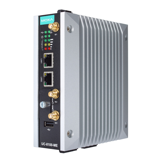
Page 9: Appearance
UC-8112-ME-T Series Hardware Hardware Introduction Appearance Front View Top View Bottom View Dimensions [units: mm (in)]... -
Page 10: Led Indicators
UC-8112-ME-T Series Hardware Hardware Introduction LED Indicators Refer to the following table for information about each LED. LED Name Color Function Steady On USB device is connected and working normally. Green USB device is not connected. Steady On SD Card inserted and working normally. Green SD Card is not detected. -
Page 11: Diagnosing Device And Subsystem Failures
The red LED will start blinking once you press the function button (FN). Keep the button pressed until the green LED is lit for the first time and then release the button to enter diagnostic mode to check which peripherals are available on the UC-8112-ME-T-LX. When the diagnostic program is running, the red LED will blink. Status... -
Page 12: Placement Options
UC-8112-ME-T Series Hardware Hardware Introduction WARNING There is a risk of explosion if the battery is replaced with an incorrect battery type. Placement Options There are two sliders on the back of the unit for DIN rail and wall mounting. DIN-Rail Mounting 1. -
Page 13: Wall Mounting (Optional)
UC-8112-ME-T Series Hardware Hardware Introduction Wall Mounting (Optional) 1. Remove the four screws on the side-panel silver cover of the device 2. Place the wall-mount brackets on the silver cover and fasten the screws as shown below. Use only the screws provided in the wall-mounting kit package. -
Page 14: Hardware Connection Description
Hardware Connection Description This section describes how to connect the UC-8112-ME-T to a network and connect various devices to the UC-8112-ME-T. The following topics are covered in this chapter: Wiring Requirements Connecting the Power Grounding the Unit ... -
Page 15: Wiring Requirements
UC-8112-ME-T Series Hardware Hardware Connection Description Wiring Requirements In this section, we describe how to connect various devices to the embedded computer. You must pay attention to the following common safety precautions, before proceeding with the installation of any electronic device: •... -
Page 16: Connecting To The Console Port
UC-8112-ME-T Series Hardware Hardware Connection Description ATTENTION This product is intended to be mounted to a well-grounded mounting surface, such as a metal panel. SG: The Shielded Ground (sometimes called Protected Ground) contact is the bottom contact of the 3-pin power terminal block connector when viewed from the angle shown here. -
Page 17: Connecting To A Serial Device
UC-8112-ME-T Series Hardware Hardware Connection Description Connecting to a Serial Device Use certified serial cables to connect the UC-8112-ME-T to serial devices. The serial ports of the UC-8112-ME-T use the 5-pin terminal block. The ports can be configured by software for RS-232, RS-422, or 2-wire RS-485. The pin assignments are shown in the following table: Terminal Block RS-232/422/485 Pinouts... -
Page 18: Installing The Cellular Module
UC-8112-ME-T Series Hardware Hardware Connection Description Installing the Cellular Module The UC-8112-ME-T is provided with a PCIe socket for installing a cellular module. To install the cellular module, do the following: 1. Remove the four screws on the DIN-rail mounting 2. - Page 19 UC-8112-ME-T Series Hardware Hardware Connection Description 7. Check the contents of the cellular module package. The package should contain the items shown below: 8. Remove the metal cover of the computer and locate the cellular module socket. 9. Remove the screw next to the socket and replace it with the bronze screw (in the package) as shown below:...
- Page 20 UC-8112-ME-T Series Hardware Hardware Connection Description 10. Attach one thermal pad to the cellular module cover and the other thermal pad to the module pad. 11. Attach the cellular module to the module pad. 12. Mount the module cover on the cellular module and use screws on both sides to secure the cover.
- Page 21 UC-8112-ME-T Series Hardware Hardware Connection Description 13. Insert the module into the socket and secure it using a screw from the package. 14. Connect antenna cables to the cellular module. There are three antenna connectors on the cellular module: W1 and W3 are for cellular antennas and W2 is for GPS antenna.
- Page 22 UC-8112-ME-T Series Hardware Hardware Connection Description 15. Insert the antenna connectors through the antenna cable holes on the front panel of the cover as shown below: 16. Secure the antenna connectors to the cover using a locking washer and nut as shown below: 17.
- Page 23 UC-8112-ME-T Series Hardware Hardware Connection Description 18. Plug the antenna onto the connector. 19. Replace the cover of the computer and fasten the screws to secure the cover. 3-10...
-
Page 24: Regulatory Approval Statements
Regulatory Approval Statements This device complies with part 15 of the FCC Rules. Operation is subject to the following two conditions: (1) This device may not cause harmful interference, and (2) this device must accept any interference received, including interference that may cause undesired operation.
Need help?
Do you have a question about the UC-8112-ME-T-LX and is the answer not in the manual?
Questions and answers