
Related Manuals for Moxa Technologies UC-8410A


Summary of Contents for Moxa Technologies UC-8410A
- Page 1 UC-8410A Hardware User’s Manual Version 2.2, April 2021 www.moxa.com/product © 2021 Moxa Inc. All rights reserved.
- Page 2 UC-8410A Hardware User’s Manual The software described in this manual is furnished under a license agreement and may be used only in accordance with the terms of that agreement. Copyright Notice © 2021 Moxa Inc. All rights reserved. Trademarks The MOXA logo is a registered trademark of Moxa Inc.
-
Page 3: Table Of Contents
LED Indicators ............................ 2-3 Diagnostic LEDs .......................... 2-4 Reset Button ............................2-4 Real-time Clock ..........................2-5 Mounting Options ..........................3-1 Installing the UC-8410A ........................3-2 Wall or Cabinet ........................... 3-2 DIN Rail ............................. 3-3 Hardware Connection Description ..................... 4-1 Wiring Requirements ........................... 4-2 Connecting the Power ......................... -
Page 4: Introduction
Introduction Thank you for purchasing the Moxa UC-8410A RISC-based dual-core ready-to-run embedded computer. This manual introduces the hardware features of the computer and provides step-by-step instructions on installing and configuring the hardware. The following topics are covered in this chapter: ... -
Page 5: Overview
10/100/1000 Mbps Ethernet ports, four digital input and four digital output channels, and a wireless communication slot (not available in the –NW model). In addition, the UC-8410A is provided with an mSATA slot for storage expansion, and 2 USB ports for additional memory (such as a USB flash drive). The computer is built using a NXP Cortex-A7 dual-core 1 GHz RISC CPU. -
Page 6: Specifications
UC-8410A HW UM Introduction Specifications NOTE For the product specifications, refer to www.moxa.com. -
Page 7: Appearance And Dimensions
Appearance and Dimensions The following topics are covered in this chapter: Appearance Dimensions LED Indicators Diagnostic LEDs Reset Button Real-time Clock... -
Page 8: Appearance
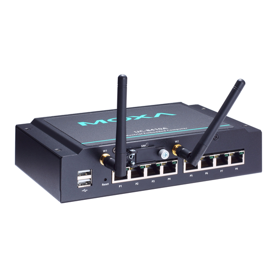
UC-8410A HW UM Appearance and Dimensions Appearance Front View NOTE The -NW model is not provided with the antenna connectors and SIM card socket. However, all models come with a cover. Rear View Left-Side View... -
Page 9: Dimensions
UC-8410A HW UM Appearance and Dimensions Dimensions Unit: mm (inch) LED Indicators Refer to the following table for information about the LEDs: LED Name Status Function Power Green Power is on No power input or any other power error Ready... -
Page 10: Diagnostic Leds
File system corrupted Blinking Blinking TPM device issue Reset Button The Reset button returns the UC-8410A to its factory default configuration and also performs the system diagnostic function. Please check the table below for details: Function Button Operation Self-diagnosis The Red LED will start blinking once you press the Reset button. Keep the button pressed until the Green LED lights up for the first time and then release the button to enter the diagnostic mode. -
Page 11: Real-Time Clock
Flash ROM. For the Windows CE 6.0 OS, all registry configurations will revert to the factory default. Real-time Clock The UC-8410A’s real-time clock is powered by a lithium battery. We strongly recommend that you do not replace the lithium battery without help from a qualified Moxa support engineer. If you need to change the battery, contact the Moxa RMA service team. -
Page 12: Mounting Options
Mounting Options The following topics are covered in this chapter: Installing the UC-8410A Wall or Cabinet DIN Rail... -
Page 13: Installing The Uc-8410A
Wall or Cabinet The two metal brackets included with the UC-8410A can be used to attach it to a wall or the inside of a cabinet. Use two screws per bracket to attach the brackets to the bottom panel of the UC-8410A. -
Page 14: Din Rail
UC-8410A HW UM Mounting Options DIN Rail The DIN-rail mounting kit includes a black plate, a silver DIN-rail mounting plate, and six screws. To install the computer on a DIN rail, do the following: Find the two screw holes on the bottom side of the computer. - Page 15 To install the computer on a DIN rail, follow these steps: Step 1—Insert the upper lip of the mounting plate into the DIN rail. Step 2—Press the UC-8410A computer towards the DIN rail until it snaps into place. To remove the computer from the DIN rail, follow these steps: Step 1—Pull down the latch on the DIN-rail mounting...
-
Page 16: Hardware Connection Description
Hardware Connection Description This section describes how to connect the UC-8410A to serial devices. The following topics are covered in this chapter: Wiring Requirements Connecting the Power Connecting to the Network Connecting to a Serial Device ... -
Page 17: Wiring Requirements
We strongly recommend that you label wiring to all devices in the system for easy identification. Connecting the Power The UC-8410A has a 3-pin terminal block for a 12 to 48 VDC power input. The following figures show how the power input interface connects to an external power source. If the power is properly supplied, the Ready LED will illuminate a solid Green color after 30 to 60 seconds have passed. -
Page 18: Connecting To The Network
Connect one end of the Ethernet cable to one of the UC-8410A’s 10/100/1000 Mbps Ethernet ports (8-pin RJ45) and the other end of the cable to the Ethernet network. If the cable is properly connected, the UC-8410A will indicate a valid connection to the Ethernet in the following ways:... -
Page 19: Connecting To The Console Port
UC-8410A HW UM Hardware Connection Description Connecting to the Console Port The UC-8410A’s console port is a 4-pin pin header RS-232 port. Refer to the following figure for the pin assignments of the console port cable: Serial Console Port and Pinouts... -
Page 20: Installing The Sd Card And Msata Card
Hardware Connection Description Installing the SD Card and mSATA Card The UC-8410A comes with a SD card slot and an mSATA socket for storage expansion. To replace or install the SD card, or to install an mSATA card, follow these steps: 1. -
Page 21: Di/Do
UC-8410A HW UM Hardware Connection Description DI/DO The UC-8410A has 4 channels for digital outputs and 4 channels digital inputs. The I/O pinouts are shown in the following figures: Digital Input Wiring Dry Contact Wet Contact NOTE If you are using wet contacts, you must connect the “COM” pin to power. -
Page 22: Installing The Wireless Modules (Not Available In The -Nw Module)
To install a wireless module you must first remove the four screws on the top panel, two screws on the front panel, and two screws on the rear panel, and remove the top cover of the UC-8410A. See the following figures... - Page 23 UC-8410A HW UM Hardware Connection Description Follow these steps to install the Wi-Fi module. 1. Find the location of the module socket. 2. Insert the module in the socket and fasten the two black screws on to the module. 3. Attach one end of the Wi-Fi cable to the connector marked CH0 and connect the other end of the cable to the W1 connector apperture on the front panel of the computer.
- Page 24 UC-8410A HW UM Hardware Connection Description 4. Pass the antenna mount’s threaded connection ring through the mounting hole, hold the locking washer against the front panel and secure the antenna connector by tightening the nut onto the threaded protection ring.
-
Page 25: Installing The Cellular Module
UC-8410A HW UM Hardware Connection Description Installing the Cellular Module The package includes 1 cellular module, 2 cellular/GPS antenna cables and connectors, 2 thermal pads, 2 screws, 2 locking washers, and 2 nuts. Follow these steps to install the cellular module: 1. - Page 26 UC-8410A HW UM Hardware Connection Description 2. Stick one of the thermal pad on the module socket. Remove the plastic cover on one side of the thermal pad and the blue cover on the other side before sticking the thermal pad to the socket.
- Page 27 UC-8410A HW UM Hardware Connection Description 4. Find the three cable connectors below the module. Note that G is for the GPS antenna, and N (in the middle) is for the cellular antenna. 5. Attach one end of the cellular antenna cable to the connector marked N and connect the other end of the cable to the W1 apperture on the front panel of the computer.
- Page 28 UC-8410A HW UM Hardware Connection Description 7. Secure the antenna connector by tightening the nut onto the threaded protection ring. 8. Stick the other thermal pad on to the module and check to make sure the internal antenna wires are securely connected to the cellular module.
-
Page 29: Installing The Sim Card
UC-8410A HW UM Hardware Connection Description Installing the SIM Card Follow these steps to install the SIM card for the cellular module. 1. Unfasten the screw on the SIM card holder cover located on the front panel of the computer. -
Page 30: Regulatory Approval Statements
Regulatory Approval Statements This device complies with part 15 of the FCC Rules. Operation is subject to the following two conditions: (1) This device may not cause harmful interference, and (2) this device must accept any interference received, including interference that may cause undesired operation.
Need help?
Do you have a question about the UC-8410A and is the answer not in the manual?
Questions and answers