
Related Manuals for Moxa Technologies UC-8100-ME-T Series


Summary of Contents for Moxa Technologies UC-8100-ME-T Series
- Page 1 UC-8100-ME-T Series Hardware User Manual Version 2.2, August 2022 www.moxa.com/product © 2022 Moxa Inc. All rights reserved.
- Page 2 UC-8100-ME-T Series Hardware User Manual The software described in this manual is furnished under a license agreement and may be used only in accordance with the terms of that agreement. Copyright Notice © 2022 Moxa Inc. All rights reserved. Trademarks The MOXA logo is a registered trademark of Moxa Inc.
-
Page 3: Table Of Contents
Table of Contents Introduction ........................... 4 Overview ............................4 Model Descriptions ........................... 4 Package Checklist ..........................4 Product Features..........................4 Specifications ..........................5 Hardware Block Diagram ........................5 Hardware Introduction ........................6 Appearance............................. 6 Dimensions [units: mm (in)] ....................... 7 LED Indicators .......................... -
Page 4: Introduction
1. Introduction The UC-8100-ME-T Series computing platform is designed for embedded data acquisition applications. The computer comes with two RS- 232/422/485 serial ports and dual 10/100 Mbps Ethernet LAN ports, as well as a Mini PCIe socket to support cellular modules. These versatile communication capabilities let users efficiently adapt the UC-8100-ME-T to a variety of complex communications solutions. -
Page 5: Specifications
Specifications NOTE The latest specifications for Moxa’s products can be found at https://www.moxa.com. Hardware Block Diagram UC-8100-ME-T Series Hardware User Manual... -
Page 6: Hardware Introduction
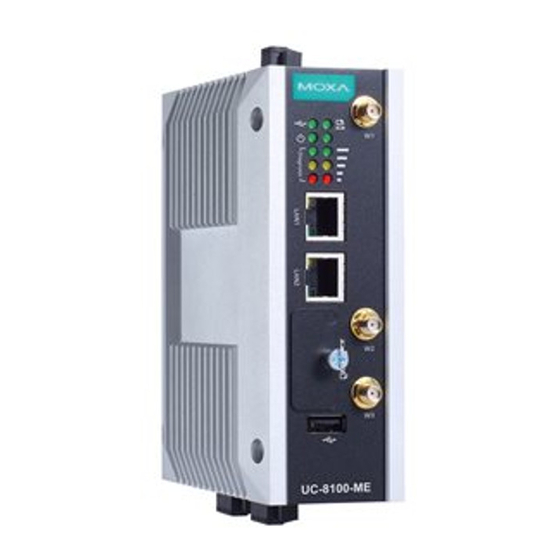
In this chapter, we provide basic information about the embedded computer’s hardware and its various components. Appearance Front View Top View Bottom View UC-8100-ME-T Series Hardware User Manual... -
Page 7: Dimensions [Units: Mm (In)]
Wireless Signal 2 (Yellow + Red): Good Strength 1 (Red): Poor Wireless module is not detected. Green Programmable These 3 LEDs are programmable. Refer to the “Default Yellow Diagnostic LEDs Programmable Button Operations” section for details. UC-8100-ME-T Series Hardware User Manual... -
Page 8: Default Programmable Button Operations
If you observe any of the following issues, check the item indicated by the LEDs. Status Red LED Yellow LED Green LED CPU usage (over 90%) Blinking RAM usage (over 90%) Disk usage (over 90%) Blinking File system corrupted Blinking Blinking UC-8100-ME-T Series Hardware User Manual... -
Page 9: Reset To Factory Default
Moxa support engineer. If you need to change the battery, contact the Moxa RMA service team. WARNING There is a risk of explosion if the battery is replaced with an incorrect battery type. UC-8100-ME-T Series Hardware User Manual... -
Page 10: Placement Options
Insert the top of the DIN rail into the slot just below the upper hook of the DIN-rail bracket. Latch the unit firmly on to the DIN rail as shown in the illustrations below. Push the slider back into place. UC-8100-ME-T Series Hardware User Manual... -
Page 11: Wall Mounting (Optional)
Place the wall-mount brackets on the silver cover and fasten the screws as shown below. Use only the screws provided in the wall-mounting kit package. ATTENTION The wall-mounting kit is not included in the package and must be purchased separately. UC-8100-ME-T Series Hardware User Manual... -
Page 12: Hardware Connection Description
If the current goes above the maximum ratings, the wiring could overheat, causing serious damage to your equipment. Temperature Caution! Be careful when handling the unit. When the unit is plugged in, the internal components generate heat, and consequently the outer casing may be hot to touch by hand. UC-8100-ME-T Series Hardware User Manual... -
Page 13: Connecting The Power
It is essential that only the supplied power cord be used. You are cautioned that changes or modifications not expressly approved by the party responsible for compliance could void your authority to operate the equipment. UC-8100-ME-T Series Hardware User Manual... -
Page 14: Connecting To The Console Port
ME-T use the 5-pin terminal block. The ports can be configured by software for RS-232, RS-422, or 2-wire RS-485. The pin assignments are shown in the following table: Terminal Block RS-232/422/485 Pinouts RS-232 RS-422 RS-485 TXD+ – TXD- – RXD+ RXD- UC-8100-ME-T Series Hardware User Manual... -
Page 15: Inserting The Sd And Sim Card
SD card. USB Port The UC-8100-ME-T is provided with 1 USB 2.0 full speed port (OHCI), type A connector, which supports a keyboard or mouse, as well as an external flash disk for storing data. UC-8100-ME-T Series Hardware User Manual... -
Page 16: Installing The Cellular Module
Remove the four screws on the silver cover on Remove the screw on metal cover. the right panel and take off the cover. Remove the three screws on the top panel. Remove the two screws on the bottom panel. UC-8100-ME-T Series Hardware User Manual... - Page 17 Check the contents of the cellular module package. The package should contain the items shown below: Remove the metal cover of the computer and locate the cellular module socket. UC-8100-ME-T Series Hardware User Manual...
- Page 18 Remove the screw next to the socket and replace it with the bronze screw (in the package) as shown below: 10. Attach one thermal pad to the cellular module cover and the other thermal pad to the module pad. 11. Attach the cellular module to the module pad. UC-8100-ME-T Series Hardware User Manual...
- Page 19 13. Insert the module into the socket and secure it using a screw from the package. 14. Connect antenna cables to the cellular module. There are three antenna connectors on the cellular module: W1 and W3 are for cellular antennas and W2 is for GPS antenna. UC-8100-ME-T Series Hardware User Manual...
- Page 20 16. Secure the antenna connectors to the cover using a locking washer and nut as shown below: 17. Arrange the antenna cables and use a cable tie to attach the cables to the bronze screw. You may cut the cable tie if it is too long. UC-8100-ME-T Series Hardware User Manual...
- Page 21 18. Plug the antenna onto the connector. 19. Replace the cover of the computer and fasten the screws to secure the cover. UC-8100-ME-T Series Hardware User Manual...
-
Page 22: Regulatory Approval Statements
European Community WARNING This is a class A product. In a domestic environment this product may cause radio interference in which case the user may be required to take adequate measures. UC-8100-ME-T Series Hardware User Manual...
Need help?
Do you have a question about the UC-8100-ME-T Series and is the answer not in the manual?
Questions and answers