Advertisement
Quick Links
Advertisement

Related Manuals for ESAB MIG400iCCCV


Summary of Contents for ESAB MIG400iCCCV
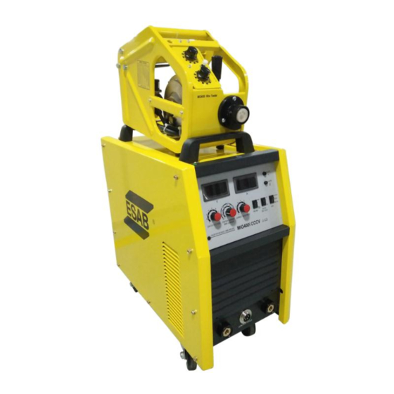
- Page 1 MIG400iCCCV INVERTER MIG/MMA Welding Power Source Instruction manual...
- Page 2 MIG400iCCCV INVERTER WELDING POWER SOURCE Instruction manual Installation, Operation & General maintenance...
-
Page 3: Table Of Contents
CONTENTS Item Page No. SAFETY RATING AND INSTALLATION CAUTIONS FOR INSTALLATION WELDING OPERATIONS WIRING DIAGRAM TROUBLESHOOTING PARTS LIST AND EXPLODED VIEW 12-14 ESAB INDIA LOCATIONS AND CONTACT DETAILS... -
Page 4: Safety
SAFETY Users of ESAB welding equipment have the ultimate responsibility for ensuring that anyone who works on or near the equipment observes all the relevant safety precautions. Safety precautions must meet the requirements that apply to this type of welding equipment. The following recommendations should be observed in addition to the standard regulations that apply to the workplace. - Page 5 WARNING Arc welding and cutting can be injurious to yourself and others. Take precautions when welding. Ask for your employer’s safety practices which should be based on manufacturers’ hazard data. ELECTRIC SHOCK – Can kill • Install and earth the welding unit in accordance with applicable standards.
- Page 6 RATING RATING OF MIG400iCCCV INVERTER WELDING POWER SOURCE CHARACTERISTICS CONSTANT VOLTAGE/ CURRENT TYPE Input: SUPPLY VOLTAGE, PHASE & FREQUENCY 415V± 15%, 3Phase, 50 Hz, AC MAXIMUM INPUT CURRENT 26.6 A Output: OUTPUT CURRENT RANGE DC 40-400A VOLTAGE RANGE 16-34 V DC...
-
Page 7: Cautions For Installation
CAUTIONS FOR INSTALLATION Provide a Switch Box for every Welding Power Source, and use designated fuse Tolerance of Power Voltage Variation is 10% of rated input voltage. a) Installation place Install in the place where less moisture and dust exist. Avoid direct sunlight and rain, and maintain ambient temperature within –10 to +45 C as much as... -
Page 8: Welding Operations
WELDING OPERATIONS 1. Current meter 1. Power switch 2. Voltage meter 2. Heater socket AC110V) 3. Crater Current 3. Controlling power trip (3A) 4. Crater Voltage 4. Fan 5. MMA/ MIG switch 5. Earthing bolt 6. Wire feeder control circuit socket 6. - Page 9 MIG MODE Put MMA/ MIG switch on power source in MIG mode. Crater Control (2T/4T) Usually there is a crater at the end of welding. Adjust Crater Voltage and Current to fill up the crater by arc ending current (less than 40%-70% of welding current) and improve the welding quality.
- Page 10 Control on wire Feeder 1. Welding Current Setting. 2. Wire Inch Push Button. 3. Welding Voltage Setting. MMA MODE Put MMA/MIG switch on power source in MMA mode. Welding current can be set by MMA current setting knob on the power source.
-
Page 12: Troubleshooting
TROUBLESHOOTING No. Breakdown Analysis Solutions Protecting Thermal reply is broken. Replace thermal relay. indicating light The machine is Restart work when the temperature overheated. returns to normal level. Fan is defective. / The Fan doesn’t work connecting lead is Replace fan, /Reconnect the lead. disconnected. -
Page 13: Parts List And Exploded View
MAIN CONTROL BRD(MIG400iCCCV) 0800660005 CONTROL TRANSF. 1(MIG400iCCCV) 0800660006 PWM CONTROL WIRE(MIG400iCCCV) 0800660007 CONTROL TRANSF. 2(MIG400iCCCV) 0800660008 TOP PANEL(MIG400iCCCV) 0800660009 TOP PANEL STRENGT RIB(MIG400iCCCV) 0800660010 COMMON MODE CHOKE(MIG400iCCCV) 0800660011 PWM AND DRIVE BRD(MIG400iCCCV) 0800660012 CUR&VOLT FEEDBACK WIRE(MIG400iCCCV) 0800660013 MOUNTING PANEL(MIG400iCCCV) 0800660014 CUR.INDUCTANCE SUPP(MIG400iCCCV) - Page 14 AVIATION SOCKET(MIG400iCCCV) 0800660044 SHUNT(MIG400iCCCV) 0800660045 RESISTANCE(MIG400iCCCV) 0800660046 PANEL(MIG400iCCCV) 0800660047 WAVE SWITCH(MIG400iCCCV) 0800660048 POTENTIOMETER KNOB(MIG400iCCCV) 0800660049 WAVE SWITCH(MIG400iCCCV) 0800660050 DIG.DISPLAY CUR MTR(MIG400iCCCV) 0800660051 LUMINOUS DIODE(MIG400iCCCV) 0800660052 LUMINOUS DIODE(MIG400iCCCV) 0800660053 LEFT PANEL(MIG400iCCCV) 0800660054 OUTPUT ABSORB BRD(MIG400iCCCV) COMMUTATION 0800660055 INDUCTANCE(MIG400iCCCV) 0800660056 SEC. ABSORB BOARD(MIG400iCCCV)
- Page 16 Web: www.esabindia.com...
Need help?
Do you have a question about the MIG400iCCCV and is the answer not in the manual?
Questions and answers