Sign In
Upload
Download
Add to my manuals
Delete from my manuals
Share
URL of this page:
HTML Link:
Bookmark this page
Add
Manual will be automatically added to "My Manuals"
Print this page
×
Bookmark added
×
Added to my manuals
Manuals
Brands
ESAB Manuals
Welding System
MIG 301i
Instruction manual
ESAB MIG 301i Instruction Manual
Inverter mig welding power source
Hide thumbs
1
2
Table Of Contents
3
4
5
6
7
8
9
10
11
12
13
14
15
16
17
page
of
17
Go
/
17
Contents
Table of Contents
Bookmarks
Advertisement
Quick Links
1
Technical Data
2
Part List and Exploded View
Download this manual
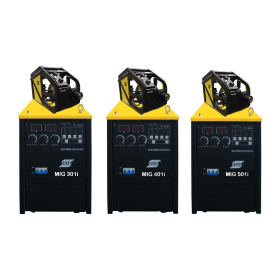
MIG 301i / 401i / 501i
INVERTER MIG
Welding Power Source
Instruction manual
Table of
Contents
Previous
Page
Next
Page
1
2
3
4
5
Advertisement
Need help?
Do you have a question about the MIG 301i and is the answer not in the manual?
Ask a question
Questions and answers
Related Manuals for ESAB MIG 301i
Welding System ESAB Mig 325 Instruction Manual
(17 pages)
Welding System ESAB Origo Mig 320 Instruction Manual
(16 pages)
Welding System ESAB Origo Mig 320 Instruction Manual
(24 pages)
Welding System ESAB Origo Mig 3001i Instruction Manual
(20 pages)
Welding System ESAB Mig 300i Instruction Manual
(24 pages)
Welding System ESAB Aristo Mig C3000i Instruction Manual
(24 pages)
Welding System ESAB Origo Mig 410 Instruction Manual
(22 pages)
Welding System ESAB Arc 4000i Service Manual
Aristo; origo (78 pages)
Welding System ESAB Aristo Mig U4000i Instruction Manual
(28 pages)
Welding System ESAB Mig 4002cw Service Manual
(64 pages)
Welding System ESAB Origo Mig 4002cw Instruction Manual
(27 pages)
Welding System ESAB Caddy Mig C200i Service Manual
Machine for mig/mag welding (50 pages)
Welding System ESAB Caddy Mig C200i Instruction Manual
(26 pages)
Welding System ESAB Buddy Mig 500i Instruction Manual
(16 pages)
Welding System ESAB Aristo Mig 4004i Pulse Instruction Manual
(34 pages)
Welding System ESAB Origo Mig 4004i A44 Instruction Manual
(28 pages)
This manual is also suitable for:
Mig 401i
Mig 501i
Print
Rename the bookmark
Delete bookmark?
Delete from my manuals?
Login
Sign In
OR
Sign in with Facebook
Sign in with Google
Upload manual
Upload from disk
Upload from URL


Need help?
Do you have a question about the MIG 301i and is the answer not in the manual?
Questions and answers