Table of Contents
Advertisement
Quick Links
Instructions – Parts List
Parts
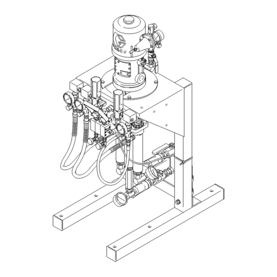
PRESIDENT HYDRA-CATr FIXED RATIO
Proportioning Pumps
3000 psi (21 MPa, 210 bar) Maximum Working Pressure
Two or Three Displacement Pump Models in Various Mix Ratios,
Pressure Ratios, and Flow Volume
Available as Bare Pumps, or as Wall-Mounted* or Free-Standing
Models
*Includes Mixing Manifolds, Automatic Pressure Relief Valves, Check Valves, Pressure Gauges, and
Regulators.
For models that are
see pages 6 and 7.
Read warnings and instructions.
See page 2 for Table of Contents and
page 6 for List of Models.
GRACO INC. P.O. BOX 1441 MINNEAPOLIS, MN 55440-1441
Copyright 1993, Graco Inc. is registered to I.S. EN ISO 9001
certified and
approved
308224E
02884A
Advertisement
Table of Contents

Related Manuals for Graco PRESIDENT HYDRA-CAT 231657


Summary of Contents for Graco PRESIDENT HYDRA-CAT 231657
- Page 1 6 and 7. Read warnings and instructions. See page 2 for Table of Contents and page 6 for List of Models. 02884A GRACO INC. P.O. BOX 1441 MINNEAPOLIS, MN 55440-1441 Copyright 1993, Graco Inc. is registered to I.S. EN ISO 9001...
-
Page 2: Table Of Contents
Plural Component Materials Hazard Graco, Inc. does not manufacture or supply any of the reactive chemical materials that may be used in this equip- ment and is not responsible for their effects. Because of the vast number of chemicals that could be used and their varying chemical reactions, before using this equipment, the buyer and the user should determine all facts relating to the materials used, including any of the potential hazards involved. -
Page 3: Symbols
D Read all instruction manuals, tags, and labels before operating the equipment. D Use the equipment only for its intended purpose. If you are not sure, call your Graco distributor. D Do not alter or modify this equipment. Use genuine Graco parts and accessories. - Page 4 WARNING INJECTION HAZARD Spray from the valve, leaks or ruptured components can inject fluid into your body and cause ex- tremely serious injury, including the need for amputation. Fluid splashed in the eyes or on the skin can also cause serious injury. D Fluid injected into the skin is a serious injury.
- Page 5 WARNING FIRE AND EXPLOSION HAZARD Improper grounding, poor ventilation, open flames or sparks can cause a hazardous condition and re- sult in a fire or explosion and serious injury. D Ground the equipment and the object being sprayed. Refer to Ground the Pumps on page 10. D If there is any static sparking or you feel an electric shock while using this equipment, stop spray- ing immediately.
-
Page 6: List Of Models
Column A gives the maximum fluid pressure developed at 100 psi (0.7 MPa, 7 bar) of incoming air pressure. Column B gives the minimum working pressure required for all system components, based on the automatic relief valve settings. Components included by Graco with the models listed meet or exceed this requirement. Models with Two Displacement Pumps... - Page 7 List of Models Models with Three Displacement Pumps Maximum Pump Minimum Nominal Flow Normal Fluid Pressure Component Volume Model No. Pressure at 100 psi (7 bar) Air Working Pressure @ 40 cpm Ratio Ratio Mix Ratio (Fluid to Air) Bare Wall Stand 231657**...
-
Page 8: Typical Installation
For assistance in designing your system, contact your Graco distributor. Light Viscosity System Two Displacement Pumps, 5:1 Ratio Feed Pumps... - Page 9 For assistance in designing your system, contact your Graco distributor. Heavy Viscosity Heated System Three Displacement Pumps, 10:1 Ratio Feed Pumps...
-
Page 10: Installation
For a safe and Locate the bracket about 5 ft (1.5 m) above the floor. efficient system, Graco recommends that the air and fluid components supplied with the Wall Mount and Ground the Pumps Cart Mount models also be used in customized systems. - Page 11 Installation Air Control Accessories Automatic Pressure Relief Valves Install the accessories in the order shown in Fig. 4. WARNING Mount only the air regulator (E) and a master air valve (A) at the pump. Mount all other accessories on sepa- To reduce the risk of component rupture, which rate wall brackets to reduce stress on the pump inlet.
- Page 12 Installation NOTE: If you mount the pump on a wall, turn the displacement pump inlet assemblies (CC) to face forward, rather than backwards as shown in Fig. 6. Connect Fluid Supply Hoses For Two Displacement Pump Models 1. Connect the resin supply hose (EE) to the 3/4 npt swivel inlet (37B) for the resin displacement pump.
-
Page 13: Installation - Optional Fluid Heaters
Installation – Optional Fluid Heaters All Models NOTE: For systems requiring one heater for each fluid, see page 38 to order the heaters and required 201a plumbing (items 201 to 205). 201b 1. Mount a heater to each side of the mounting bracket using the three screws (201a) and lock- washers (201b) supplied with each heater. - Page 14 Installation – Optional Fluid Heaters 23 (N) 204B 205A HARD HARD 202B 202A HARD HEATE HEATE 203A 203B 02894 Fig. 10 For Three Displacement Pump Models NOTE: You must provide two hoses (FA, FB in Fig.10) and fittings to run from the heater outlets to the mixer manifold inlets.
-
Page 15: Installation - Optional Solvent Pump
Installation – Optional Solvent Pump NOTE: The optional solvent pump is not offered as a 4. Couple the hose (303) and couplings (302). kit; order parts as needed. The optional parts shown Connect the hose (303) to the adapter (301). here are listed on page 39. -
Page 16: Flushing
Flushing When to Flush the System How to Operate the Mixer Manifold To open or close the mixer manifold (N) fluid valves D Flush the system before its first use to remove the (LL) push the handle (KK) down to open and up to light oil which was left in after factory testing. - Page 17 Flushing How to Flush the System To flush the solvent valves . . . 11. Open the hardener solvent flush valve (N1) on the WARNING mixer manifold (N). See Fig. 13. a. Be sure the solvent pump air regulator (E4) is If your system is equipped with heaters, always at minimum pressure.
-
Page 18: Operation
02948A Fig. 16 Keep each displacement pump throat packing nut (JJ) Monitor the Material Supply filled with Graco ISO Pump Oil to help prevent fluid from drying on the displacement rod and damaging the CAUTION pump packings. See Fig. 15. - Page 19 Operation Startup 6. Open the mixer manifold (N) and trigger the dispense valve (S). WARNING 7. Set the air pressure to the feed pumps at 88 psi (0.6 MPa, 6 bar) or 25% of proportional pressure To reduce the risk of serious bodily injury, including at the fluid outlets, whichever is less.
- Page 20 Operation Checking the Mix Ratio 10. While observing the pump outlet gauges (J2), adjust the resin and hardener drain valves (P1,P2) NOTE: Since this is a fixed ratio system, you typically until the gauges show your normal operating do not have to check the mix ratio. pressure.
-
Page 21: Shutdown And Care Of The System
Shutdown and Care of the System Pressure Relief Procedure If you suspect that the nozzle or hose is completely clogged, or that pressure has not been fully relieved after following the steps above, very slowly loosen the WARNING nozzle or hose end coupling and relieve pressure gradually, then loosen completely. -
Page 22: Troubleshooting
Troubleshooting WARNING WARNING To reduce the risk of serious bodily injury, always Never operate the pump with the air motor plate follow the Pressure Relief Procedure on page 21 removed, to reduce the risk of serious bodily injury, whenever you shut off the pump, when checking or including amputation, from moving parts inside the servicing any part of the dispensing system, when air motor housing. - Page 23 Troubleshooting Problem Cause Solution System won’t run or Air pressure or volume too low. Increase, check air compressor. stops while running. Closed or restricted air line or air valve. Open or clean as required. Fluid valves closed. Open fluid valves. Clogged fluid hose.
-
Page 24: Service - Displacement Pump
Service – Displacement Pump Removal and Replacement Thoroughly flush the system with a solvent which is compatible to the fluid being pumped, then follow the Pressure Relief Procedure on page 21. The Flushing procedure is on page 17. Stop the pump at the bottom of its stroke. CAUTION If you are changing to a different type of fluid, com- pletely clean all of the equipment and hoses, making... - Page 25 Service – Displacement Pump Disassembly 1. Remove the locknuts (113) from the top of the yoke (114) of the two outer displacement rods. See Fig. 22. Unscrew the outer locknuts (122) from the top of the tie plate (123) on the two displacement pumps.
-
Page 26: Parts - Bare, Two Pumps
Parts – Bare, Two Pumps Models 231643–231646 Torque to 53–67 ft-lb (72–91 Apply anaerobic sealant and torque to 100–200 ft-lb (135–270 NSm) Torque to 14–26 ft-lb (19–35 NSm) Label 02903 308224... - Page 27 Parts – Bare, Two Pumps Models 231643–231646 Ref. Ref. Part No. Description Qty. Part No. Description Qty. 101 207352 PRESIDENT AIR MOTOR 112 101946 PIN, cotter, 0.116 OD x 1–1/2 in. see manual 306982 113 101926 LOCKNUT 1/2–20 unf 102 168418 PLATE, pump adapter w/nylon insert 103 100018...
-
Page 28: Parts - Bare, Three Pumps
Parts – Bare, Three Pumps Models 231657 and 231663 Torque to 53–67 ft-lb (72–91 NSm) Apply anaerobic sealant and torque to 100–200 ft-lb (135–270 NSm) Torque to 14–26 ft-lb (19–35 NSm) Label Apply stainless steel pipe sealant to all 02904 threaded connections. - Page 29 Parts – Bare, Three Pumps Models 231657 and 231663 Ref. Ref. Part No. Description Qty. Part No. Description Qty. 101 207352 PRESIDENT AIR MOTOR 164414 YOKE, connector tube see manual 306982 164416 WASHER, flat, 1/2 in. 102 168418 PLATE, pump adapter 101712 LOCKNUT, 5/8–11 unc (2b) 103 100018...
-
Page 30: Parts - Wall Mount, Two Pumps
Parts – Wall Mount, Two Pumps Models 231593 and 231595 Apply stainless steel pipe sealant to all threaded connections except at swivels. Included with bare pump 11,12 02905A 308224... - Page 31 Parts – Wall Mount, Two Pumps Models 231593 and 231595 Ref. Ref. Part No. Description Qty. Part No. Description Qty. see table BARE PROPORTIONAL PUMP 108233 NEEDLE (DRAIN) VALVE see parts on page 27 164259 ELBOW, street, 3/8–18 npt (f) 100960 PRESSURE GAUGE, 0–2000 psi 1/4–18 npt (f)
-
Page 32: Parts - Wall Mount, Three Pumps
Parts – Wall Mount, Three Pumps Models 231607 and 231613 Apply stainless steel pipe sealant to all threaded connections ex- cept at swivels Included with bare pump 11,12 02906A 308224... - Page 33 Parts – Wall Mount, Three Pumps Models 231607 and 231613 Ref. Ref. Part No. Description Qty. Part No. Description Qty. see table BARE PROPORTIONAL PUMP 108233 NEEDLE (DRAIN) VALVE see parts on page 29 164259 ELBOW, street, 3/8–18 npt (f) 100960 PRESSURE GAUGE, 0–2000 psi 1/4–18 npt (f)
-
Page 34: Parts - Stand Mount, Two Pumps
Parts – Stand Mount, Two Pumps Model 231618 Apply anaerobic sealant and torque to 10–15 ft-lb (14–20 NSm) See parts on pages 36 and 37 02907A 308224... - Page 35 Parts – Stand Mount, Two Pumps Models 231618 Ref. Part No. Description Qty. 231593 WALL MOUNT PUMP see parts on page 31 100321 NUT, hex, 1/2–13 unc 100018 LOCKWASHER, 1/2 in. 217297 LEG, frame 100679 SCREW, hex cap head, 1/2–13 unc (2a) x 3–1/2 in. 178473 BRACE, frame 168422...
-
Page 36: Parts- Stand Mount, Three Pumps
Parts– Stand Mount, Three Pumps Models 231632 and 231638 Apply anaerobic sealant and torque to 10–15 ft-lb (14–20 NSm) 02908A 308224... - Page 37 Parts – Stand Mount, Three Pumps Models 231632 and 231638 Ref. No. 1 Wall Ref. Model Pump Part No. Description Qty. 231632 231607 see table WALL MOUNT PUMP see parts on page 33 231638 231613 100321 NUT, hex, 1/2–13 unc 100018 LOCKWASHER, 1/2 in.
-
Page 38: Accessories
Accessories Parts for Installing Optional Heaters Viscon HP Fluid Heaters Style A The following components are recommended to install the heaters as instructed on page 13. Two displace- Model 245848, 120 Volt, Stainless Steel ment pump models need Items 201 to 204. Three 4000 psi (28 MPa, 276 bar) Maximum Working Pressure displacement pump models need Items 201 to 205 and 85_ –... - Page 39 217374 16 oz (0.13 liter) container Inlet: 1/4 in. npt(m). Outlet: 3/4: npt (m). 218656 4 gallon (18.14 liter) container Graco Throat Seal Liquid Non-evaporating liquid for wet-cup 206995 0.95 liter (1 quart) 206996 3.8 liter (1 gallon)
- Page 40 Accessories Air Control Accessories Fluid Control Accessories Bleed-Type Master Air Valve Fluid Filter 300 psi (2.1 MPa, 21 bar) Maximum Working Pressure 5000 psi (35 MPa, 350 bar) Maximum Working Pressure Relieves air trapped in the air line between the pump 60 mesh (250 micron) screen.
- Page 41 Notes 308224...
-
Page 42: Dimensions
Dimensions Mounting Hole Layout for Air Motor 0288 0.438 in. (11.12 mm) diameter 3.712 in. (92.28 mm) 7.424 in. (188.66 mm) 9.75 in. (247.65 mm) diameter 14–3/4 in. (375 mm) 30–1/4 in. (768 mm) 32–3/4 in. (832 mm) 11 in. (279 mm) 28–1/4 in. -
Page 43: Technical Data
Technical Data Pumps Air operating range 40–100 psi (0.3–0.7 MPa, 3–7 bar) Air consumption See example below Fluid inlet size 3/4 npt Fluid outlet size 3/8 npt Air inlet size 3/4 npt Maximum fluid outlet pressure 3000 psi (21 MPa, 210 bar) Maximum fluid inlet pressure 250 psi (1.7 MPa, 17 bar) Wetted parts... -
Page 44: Graco Standard Warranty
Graco distributor to the original purchaser for use. With the exception of any special, extended, or limited warranty published by Graco, Graco will, for a period of twelve months from the date of sale, repair or replace any part of the equipment determined by Graco to be defective.
Need help?
Do you have a question about the PRESIDENT HYDRA-CAT 231657 and is the answer not in the manual?
Questions and answers