Graco A Series Instructions-Parts List Manual
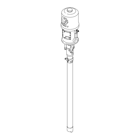
2” bung mount, 200 liter (55 gallon) drum size
Hide thumbs
Also See for A Series:
- Instructions - parts manual (52 pages) ,
- Instructions-parts list manual (48 pages) ,
- Manual (36 pages)
Advertisement
Quick Links
Distributed by:!
Corrosion
Control
Equipment
and
Supplies
Houston Office:
248 McCarty Dr.
Houston, TX 77029-1195
(713) 672-8251
Fax (713) 672-6636
1-800-CLEMTEX
www.clemtex.com
clemtex@clemtex.com
Dallas Branch:
4770 Gretna
Dallas, TX 75207
(214) 631-0584
Fax (214) 631-5824
1-800-BLAST 97
Corpus Christi Branch:
4750 Westway
Corpus Chrisi, TX 78408
(361) 882-8282
Fax (361) 882-6029
Advertisement

Subscribe to Our Youtube Channel
Related Manuals for Graco A Series


Summary of Contents for Graco A Series
- Page 1 Distributed by:! Dallas Branch: 4770 Gretna Corrosion Houston Office: Dallas, TX 75207 1-800-CLEMTEX (214) 631-0584 248 McCarty Dr. Control Fax (214) 631-5824 www.clemtex.com Houston, TX 77029-1195 Equipment 1-800-BLAST 97 clemtex@clemtex.com (713) 672-8251 Fax (713) 672-6636 Corpus Christi Branch: 4750 Westway Supplies Corpus Chrisi, TX 78408 (361) 882-8282...
- Page 2 6.2 bar (0.62 MPa, 90 psi) Maximum Air Input Pressure Read warnings and instructions. Refer to page 2 for the Table of Contents. 0359 II 1/2 G T2 GRACO INC. P.O. BOX 1441 MINNEAPOLIS, MN 55440-1441 ITS03ATEX11228 Copyright 1998, Graco Inc. is registered to I.S. EN ISO 9001...
- Page 3 D This equipment is for professional use only. D Read all instruction manuals, tags, and labels before operating the equipment. D Use the equipment only for its intended purpose. If you are uncertain about usage, call your Graco distributor. D Do not alter or modify this equipment. Use only genuine Graco parts and accessories.
- Page 4 Permanently coupled hoses cannot be repaired; replace the entire hose. D Use only Graco approved hoses. Do not remove any spring guard that is used to help protect the hose from rupture caused by kinks or bends near the couplings.
- Page 5 WARNING FIRE AND EXPLOSION HAZARD Improper grounding, poor ventilation, open flames or sparks can cause a hazardous condition and result in a fire or explosion and serious injury. D Ground the equipment and the object being sprayed. Refer to Grounding on page 5. D If there is any static sparking or you feel an electric shock while using this equipment, stop spray- ing/dispensing immediately.
- Page 6 Connect the other end of the wire to a true earth ground. For a ground wire and D Always use Genuine Graco Parts and Accessories, clamp, order Part No. 237569. available from your Graco distributor. If you supply your own accessories, be sure they are adequately sized and pressure-rated to meet the system’s...
- Page 7 Installation Typical Installation Pump Bung adapter Air line lubricator Bleed-type master air valve (required for pump) See Warning on page 7 for part number. Pump air regulator Air line filter G Bleed-type master air valve (for accessories) Electrically conductive air supply hose Air line moisture trap and drain valve Pump runaway valve Fluid drain valve (required)
- Page 8 Installation System Accessories Air Line Accessories Install the following accessories in the order shown in WARNING Fig. 2, using adapters as necessary: D Air line lubricator (C) A bleed-type master air valve (D) and a fluid drain Provides automatic air motor lubrication. valve (L) are required in your system.
- Page 9 Pressure Relief Procedure at left. relieved to prevent the system from starting or spraying accidentally. Fluid Keep the packing nut/wet-cup (S) filled with Graco under high pressure can be injected through the Throat Seal Liquid (TSL) or compatible solvent to help skin and cause serious injury.
- Page 10 Operation Flushing the Pump WARNING WARNING COMPONENT RUPTURE HAZARD To reduce the risk of overpressurizing your system, which could cause FIRE AND EXPLOSION HAZARD component rupture and serious injury, Before flushing, read the section FIRE never exceed the specified maximum air input AND EXPLOSION HAZARD on page pressure to the pump (see Technical Data on 4.
- Page 11 Troubleshooting 1. Relieve the pressure. WARNING 2. Check all possible problems and solutions before To reduce the risk of serious injury whenever you disassembling pump. are instructed to relieve pressure, always follow the Pressure Relief Procedure on page 8. Problem Cause Solution Pump fails to operate.
- Page 12 4. Mount the pump and reconnect all hoses. Reconnect the ground wire if it was disconnected during repair. Tighten the packing nut (S). Fill the wet-cup with Graco Throat Seal Liquid or compatible solvent. 5. Tighten the tie rod locknuts (7) evenly, and torque to 27 to 41 NSm (20 to 30 ft-lb).
- Page 13 Parts Part No. 239326, Series A Part Description 207352 AIR MOTOR see manual 306982 220465 DISPLACEMENT PUMP ASSY, see manual 307044 222308 BUNG ADAPTER; consists of items 4 and 5 210834 . ADAPTER 104542 . CAPSCREW 166237 ROD, tie; carbon steel; 89 mm (3.5 in.) shoulder to shoulder 101566 NUT, lock, 3/8–16...
- Page 14 Dimensions Dimension Measurement 883 mm (34.75 in.) 1454 mm (57.25 in.) 1/2 npt(f) 3/4 npt(f) 3/4 npt(f) 2 in. npt (air inlet) (fluid outlet) (bung adapter) (fluid intake) 07199 308738...
- Page 15 Technical Data Category Data Ratio 10:1 Maximum fluid working pressure 62 bar (6.2 MPa, 900 psi) Maximum air input pressure 6.2 bar (0.62 MPa, 90 psi) Fluid flow at 60 cycles per minute 11 liters/min (3 gpm) Maximum pump operating temperature 82_C (180_F) Wetted parts Refer to manual 307044.
- Page 16 Technical Data Performance Chart KEY: Fluid Outlet Pressure – Black Curves cycles per minute scfm bar, MPa Air Consumption – Gray Curves m#/min 6.2 bar (0.62 MPa, 90 psi) Air Pressure 62, 6.2 1.68 4.9 bar (0.49 MPa, 70 psi) Air Pressure 2.8 bar (0.28 MPa, 40 psi) Air Pressure To find fluid outlet pressure (bar/MPa/psi) at a specific fluid flow (lpm/gpm) and operating air...
- Page 17 With the exception of any special, extended, or limited warranty published by Graco, Graco will, for a period of twelve months from the date of sale, repair or replace any part of the equipment determined by Graco to be defective.
Need help?
Do you have a question about the A Series and is the answer not in the manual?
Questions and answers