Table of Contents
Advertisement
Quick Links
Instructions - Parts List
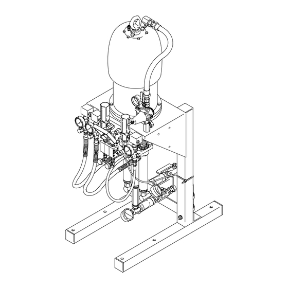
BULLDOG HYDRA-CAT
Proportioning Pumps
3000 psi (21 MPa, 207 bar) Maximum Working Pressure
Two or Three Displacement Pump Models
in Various Mix Ratios, Pressure Ratios
and Flow Volume
Available as Bare Pumps,
Wall-Mounted* or Free-Standing* Models
*Includes Mixing Manifolds, Automatic Pressure Relief Valves,
Check Valves, Pressure Gauges and Regulators
Read warnings and instructions.
For a list of models, see page 6.
Table of Contents
. . . . . . . . . . . . . . . . . . . . . . . . . . . . . . . . . . . . . . . . . . . . . .
. . . . . . . . . . . . . . . . . . . . . . . . . . . . . . . . . . . . . . . . . . .
. . . . . . . . . . . . . . . . . . . . . . . . . . . . . . . . . . .
. . . . . . . . . . . . . . . . . . . . . . . . . . . . . . . . . . . . . . . . . . . . .
. . . . . . . . . . . . . . . . . . . . . . . . . . . . . . . . . . . . . . . . . . . . . .
. . . . . . . . . . . . . . . . . . . . . . . . . . . . . . . . . . . . . . . . . . . . .
. . . . . . . . . . . . . . . . . . . . . . . . . . . . . . . . . . . . . . .
. . . . . . . . . . . . . . . . . . . . . . . . . . . . . . . . . . . . . . . . . . . . . . . .
. . . . . . . . . . . . . . . . . . . . . . . . . . . . . . . . . . . . . . . . . . .
. . . . . . . . . . . . . . . . . . . . . . . . . . . . . . . . . . . . . . . . . . .
. . . . . . . . . . . . . . . . . . . . . . . . . . . . . . . . . . . . . . . .
. . . . . . . . . . . . . . . . . . . . . . . . . . . . . . .
R
FIXED RATIO
. . . . . . . . . . . . . . . . . . . . . . .
. . . . . . . . . . . . . . . . . . . . . .
. . . . . . . . . . . . . . . . . . . . . . . .
. . . . . . . . . . . . . . . . . . . . . . . . . . .
2
6
7, 8
9
13
15
16
19
23
24
26
28
40
43
45
46
308225K
EN
02910A
Advertisement
Table of Contents

Subscribe to Our Youtube Channel
Related Manuals for Graco Bulldog Hydra-Cat Series


Summary of Contents for Graco Bulldog Hydra-Cat Series
-
Page 1: Table Of Contents
........Graco Standard Warranty... -
Page 2: Warnings
Symbols Warning Symbol Caution Symbol WARNING CAUTION This symbol alerts you to the possibility of serious This symbol alerts you to the possibility of damage to injury or death if you do not follow the instructions. or destruction of equipment if you do not follow the instructions. - Page 3 D Always wear protective eyewear, gloves, clothing and respirator as recommended by the fluid and solvent manufacturer. D Graco does not manufacture or supply any of the reactive chemical components that may be used in this equipment and is not responsible for their effects. Graco assumes no responsibility for loss, damage, expense or claims for personal injury or property damage, direct or consequential, arising from the use of such chemical components.
- Page 4 D This equipment is for professional use only. D Read all instruction manuals, tags, and labels before operating the equipment. D Use the equipment only for its intended purpose. If you are uncertain about usage, call your Graco distributor. D Do not alter or modify this equipment. Use only genuine Graco parts and accessories.
- Page 5 Notes head.notes 308225...
-
Page 6: Model Charts
Column A gives the maximum pump fluid output pressure. Column B gives the minimum working pressure required for all system components, based on the automatic relief valve settings. Components included by Graco with the models listed meet or exceed this requirement. Models with Two Displacement Pumps... -
Page 7: Typical Installations
For assistance in designing your system, contact your nearest Graco representative. Light Viscosity System Two Displacement Pumps, 5:1 Ratio Feed Pumps... -
Page 8: Typical Installations
For assistance in designing your system, contact your nearest Graco representative. Heavy Viscosity Heated System Three Displacement Pumps,... -
Page 9: Installation
For a safe and the hardener. efficient system, Graco recommends that the air and fluid components supplied with the Wall Mount and 2. Label all pumps, hoses, fluid regulators, etc. to... - Page 10 Installation Grounding 2. Air hoses: use only grounded hoses with a maxi- mum of 500 feet (150 m) combined hose length to ensure grounding continuity. WARNING FIRE AND EXPLOSION HAZARD 3. Fluid hoses: use only grounded fluid hoses. Improper grounding could cause static sparking, which could cause a fire or explosion.
- Page 11 Installation Air Control Accessories 3. Install a pump runaway valve (D) for each feed pump to automatically shut off the air to the pump if the pump accelerates beyond the pre-adjusted Install the accessories in the order shown in Fig. 4. setting.
- Page 12 Installation Automatic Pressure Relief Valves Additional System Components (continued) Install and connect the feed pumps, solvent pump, heaters, etc. Refer to the Typical Installations page 7 Two drainage bottle kits (38) are included with wall and Accessories on pages 40 and 41 for parts informa- models (unassembled) and stand mount models tion.
-
Page 13: Installation - Optional Fluid Heaters
Installation – Optional Fluid Heaters All Models NOTE: For systems requiring one heater for each fluid, see page 40 to order the heaters and required plumbing (items 201 to 205). 201a 1. Mount a heater to each side of the mounting 201b bracket using the three screws (201a) and lock- washers (201b) supplied with each heater. - Page 14 Installation – Optional Fluid Heaters 204B 205A HARD HARD 202B 202A HARD HEATER HEATER 203A 203B Fig. 10 02894 For Three Displacement Pump Models NOTE: You must provide two hoses (FA, FB in Fig.10) and fittings to run from the heater outlets to the mixer manifold inlets.
-
Page 15: Installation - Optional Solvent Pump
Installation – Optional Solvent Pump NOTE: The optional solvent pump is not offered as a 4. Couple the hose (303) and couplings (302). kit; order parts as needed. The optional parts shown Connect the hose (303) to the adapter (301). here are listed on page 41. -
Page 16: Flushing
Flushing When to Flush the System How to Operate the Mixer Manifold To open or close the mixer manifold fluid valves (LL) D Flush the system before its first use to remove the push the handle (KK) down to open and up to close. light oil which was left in after factory testing. - Page 17 Flushing How to Flush the System 7. Slowly increase the air regulator (E1) setting until the pump is running slowly. WARNING 8. Open the hardener side drain valve (P1). Open the mixer manifold handle (KK). See Fig. 13. HOT SURFACE HAZARD If your system is equipped with heaters, 9.
- Page 18 Flushing If this is a first time flush . . . WARNING 12. Repeat the flushing procedure using a solvent compatible with the fluid you are going to INJECTION HAZARD dispense. To reduce the risk of serious injury from fluid injec- When you are done flushing .
-
Page 19: Operation
4. Disengage the dispensing valve safety latch. Keep each displacement pump throat packing nut (JJ) filled with Graco ISO Pump Oil to help prevent fluid 5. Hold a metal part of the dispensing valve firmly to from drying on the displacement rod and damaging the the side of a grounded metal pail, and trigger the pump packings. - Page 20 Operation Monitor the Material Supply Check the Drainage Bottles and Hoses CAUTION WARNING Establish a rigid system for monitoring the material supply to prevent the pumps from running dry. A INJECTION HAZARD sudden lack of material in one pump may cause To reduce the risk of serious injury and property many system problems, including air entrapment, damage, regularly check and clean the drain hose...
- Page 21 Operation Startup 6. Open the mixer manifold (N) and trigger the dispense valve (S). WARNING 7. Set the air pressure to the feed pumps at 88 psi (605 kPa, 6 bar) or 25% of proportional pressure at INJECTION HAZARD the fluid outlets, whichever is less. Use the gauges To reduce the risk of serious injury, (J1) to monitor this pressure.
- Page 22 Operation Checking the Mix Ratio 11. Close the mixer manifold. Put a separate sampling container under each drain valve. WARNING 12. Open the mixer manifold to draw a sufficient sample. INJECTION HAZARD To reduce the risk of serious injury, 13. As you close the mixer manifold, check the pump follow the Pressure Relief Procedure outlet gauges (J2) again to make sure they are at on page 19 whenever you are instructed...
-
Page 23: Shutdown And Care Of The System
Shutdown and Care of the System Care of the Pump Throat Packing Nuts WARNING Keep the throat packing nuts (JJ) filled with appropri- ate lubricant and check the tightness of the packing INJECTION HAZARD nut weekly. See Fig. 19. To reduce the risk of serious injury, follow the Pressure Relief Procedure Always follow the Pressure Relief Procedure, page on page 19 whenever you are instructed... -
Page 24: Troubleshooting
Troubleshooting WARNING WARNING INJECTION HAZARD MOVING PARTS HAZARD To reduce the risk of an injury from To reduce the risk of serious injury, injection, splashing fluid, or moving including amputation, from moving parts parts, follow the Pressure Relief Proce- inside the air motor housing, never dure on page 19 if the spray tip/nozzle clogs and operate the pump with the air motor plate removed. - Page 25 Troubleshooting Problem Cause Solution System will not run or Air pressure or volume too low. Increase, check air compressor. stops while running. Closed or restricted air line or air valve. Open or clean as required. Fluid valves closed. Open fluid valves. Clogged fluid hose.
-
Page 26: Service - Displacement Pump
Service – Displacement Pump 1. Unscrew the swivel union (33) from the bottom of WARNING the center displacement pump. Unscrew the swivel unions (126) from the outer displacement pumps. INJECTION HAZARD Remove the supply manifold (125) from the outer To reduce the risk of serious injury, pumps. - Page 27 Service – Displacement Pump Disassembly 1. Remove the locknuts (113) from the top of the yoke (114) of the two outer displacement rods. See Fig. 22. Unscrew the outer locknuts (122) from the top of the tie plate (121) on the two displacement pumps.
-
Page 28: Parts
Parts – Bare, Two Pumps Model 231897 Torque to 53–67 ft-lb (72–91 NSm) Apply anaerobic sealant and torque to 100–200 ft-lb (135–270 NSm) Label 02915 308225... - Page 29 Parts – Bare, Two Pumps Model 231897 Ref. Part No. Description Qty. Ref. Part No. Description Qty. 208356 BULLDOG AIR MOTOR, 101926 LOCKNUT, 1/2–20 unf with see manual 307049 nylon insert 100428 SCREW, hex cap head, 164414 YOKE, connector tube 5/8–11 unc (2a) x 2”...
- Page 30 Parts – Bare, Three Pumps Models 231908, 231910, 231912, and 231915 Torque to 53–67 ft-lb (72–91 NSm) Apply anaerobic sealant and torque to 100–200 ft-lb (135–270 NSm) Label Apply stainless steel pipe sealant to all threaded connections. 02916 308225...
- Page 31 Parts – Bare, Three Pumps Models 231908, 231910, 231912, and 231915 Ref. Part No. Description Qty. Ref. Part No. Description Qty. 208356 BULLDOG AIR MOTOR, 164414 YOKE, connector tube see manual 307049 164416 WASHER, flat, 1/2” 100128 SCREW, hex cap head, 101712 LOCKNUT, 5/8–11 unc (2b) 5/8–11 unc (2a) x 2”...
- Page 32 Parts – Wall Mount, Two Pumps Model 231836 Apply stainless steel pipe sealant to all threaded connections except at swivels. 11,12 11, 28 02917A 308225...
- Page 33 Parts – Wall Mount, Two Pumps Models 231836 Ref. Part No. Description Qty. Ref. Part No. Description Qty. 231897 BARE PROPORTIONAL 188974 LABEL, hardener PUMP, see parts on 101748 PLUG, pipe, 3/8–18 npt(f), page 29 205712 AIR REGULATOR KIT, see 206962 CHECK VALVE, 3/8 npt parts in manual 306972...
- Page 34 Parts – Wall Mount, Three Pumps Models 231847, 231849, 231851, and 231854 Apply stainless steel pipe sealant to all threaded connections except at swivels Included with bare pump 11, 12 11, 28 02918A 308225...
- Page 35 Parts – Wall Mount, Three Pumps Models 231847, 231849, 231851, and 231854 Ref. Part No. Description Qty. Ref. Part No. Description Qty. see table BARE PROPORTIONAL 160032 NIPPLE, 3/4 npt PUMP, see parts on 102735 BALL VALVE, 3/4–14 npt(f) page 31 157785 SWIVEL UNION, 3/4 nps(f) 207651...
- Page 36 Parts – Stand Mount, Two Pumps Model 231865 Apply anaerobic sealant and torque to 10–15 ft-lb (14–20 NSm) 02919A 308225...
- Page 37 Parts– Stand Mount, Two Pumps Models 231865 Ref. Part No. Description Qty. Ref. Part No. Description Qty. 231836 WALL MOUNT PUMP, see 217297 LEG, frame parts on page 33 100679 SCREW, hex cap head, 100321 NUT, hex, 1/2–13 unc 1/2–13 unc (2a) x 3-1/2” 100018 LOCKWASHER, 1/2”...
- Page 38 Parts– Stand Mount, Three Pumps Models 231876, 231878, 231880, and 231883 Apply anaerobic sealant and torque to 10–15 ft-lb (14–20 NSm) 02920A 308225...
- Page 39 Parts – Stand Mount, Three Pumps Models 231876 through 231883 Ref. No. 1 Wall Ref. Part No. Description Qty. Model Pump 231876 231847 see table WALL MOUNT PUMP, see parts on page 35 231878 231849 100321 NUT, hex, 1/2–13 unc 231880 231851 100018...
-
Page 40: Accessories
Accessories Parts for Installing Optional Heaters Viscon HP Fluid Heaters The following components are recommended to install Style A the heaters as instructed on page 13. Two displace- Model 245848, 120 Volt, Stainless Steel ment pump models need Items 201 to 204. Three displacement pump models need Items 201 to 205 and 4000 psi (28 MPa, 276 bar) Maximum Working Pressure an additional resin and hardener hose of an... - Page 41 Inlet: 1/4” npt(m). Outlet: 3/4: npt(m). 218656 4 gallon (18.14 liter) container Grounding Wire and Clamp, 222011 Graco Throat Seal Liquid 7.6 m (25 ft) long, 1.5 mm@ (12 gauge) Non-evaporating liquid for wet-cup 206995 0.95 liter (1 quart) 206996 3.8 liter (1 gallon)
- Page 42 Accessories Air Control Accessories Controls air pressure to feed, sol- vent, or proportioning pumps. Bleed-Type Master Air Valve 1/2 npt inlets and outlets, with (2) 1/4 npt pressure gauge outlets. 300 psi (2.1 MPa, 21 bar) Maximum Working Pressure Relieves air trapped in the air line between the pump air inlet and this valve when closed.
-
Page 43: Dimensions
Dimensions Mounting Hole Layout for Air Motor 01154 3.712” (94 mm) 02910A 3.46” (88 mm) 4” (102 mm) 2” (51 mm) 5/8–11 UNC (3) for pump mounting 0.44” (11.1 mm) diameter (4) 21–1/4” (540 mm) 30–1/4” (768 mm) 32–3/4” (832 mm) 11”... - Page 44 Notes head.notes 308225...
-
Page 45: Technical Data
Technical Data Pumps Manifold assemblies Air operating range ..40–100 psi (280–700 Manifold outlets ..3/8 npt kPa, 2.8–6.37 bar) Hoses ....3/8 in. ID, PTFE, cpld 3/8 Air consumption . -
Page 46: Graco Standard Warranty
Graco distributor to the original purchaser for use. With the exception of any special, extended, or limited warranty published by Graco, Graco will, for a period of twelve months from the date of sale, repair or replace any part of the equipment determined by Graco to be defective.
Need help?
Do you have a question about the Bulldog Hydra-Cat Series and is the answer not in the manual?
Questions and answers