Table of Contents
Advertisement
Quick Links
Instructions
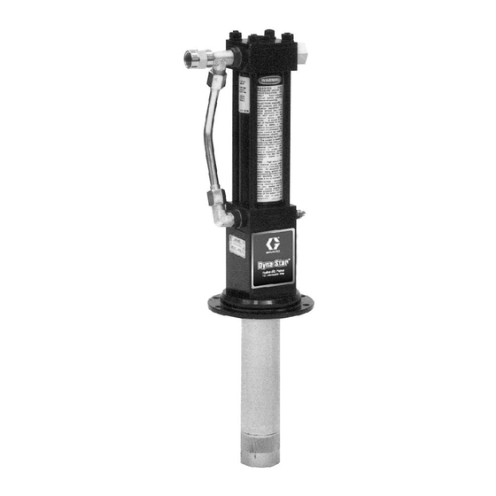
Dyna-Star
Universal Pump and
Reciprocator
For lubricating fluids only. For professional use only.
Model 236753
Series B, Stubby length
Model 239884
Series A, Reciprocator only
1500 psi (10 MPa, 120 bar) Maximum Hydraulic Inlet
Pressure
375 psi (2.6 MPa, 26 bar) Maximum Fluid Outlet
Pressure
Important Safety Instructions
Read all warnings and instructions in this
manual. Save these instructions.
The pump is designed to dispense lube products
only. Any other fluids can cause unsafe operating
conditions and result in component rupture, fire or
explosion which could cause serious injury, including
fluid injection.
™
1/4:1 Ratio
Model 236753 Shown
308390N
EN
Advertisement
Table of Contents

Related Manuals for Graco Dyna-Star B Series


Summary of Contents for Graco Dyna-Star B Series
- Page 1 Instructions ™ Dyna-Star 1/4:1 Ratio Universal Pump and 308390N Reciprocator For lubricating fluids only. For professional use only. Model 236753 Series B, Stubby length Model 239884 Series A, Reciprocator only 1500 psi (10 MPa, 120 bar) Maximum Hydraulic Inlet Pressure 375 psi (2.6 MPa, 26 bar) Maximum Fluid Outlet Pressure Important Safety Instructions...
-
Page 2: Table Of Contents
Dimensions ....... 21 Graco Standard Warranty ....22... -
Page 3: Warnings
Warnings Warnings The following warnings are for the setup, use, grounding, maintenance, and repair of this equipment. The exclama- tion point symbol alerts you to a general warning and the hazard symbols refer to procedure-specific risks. When these symbols appear in the body of this manual or on warning labels, refer back to these Warnings. Product-specific hazard symbols and warnings not covered in this section may appear throughout the body of this manual where applicable. - Page 4 Warnings WARNING EQUIPMENT MISUSE HAZARD Misuse can cause death or serious injury. • Do not operate the unit when fatigued or under the influence of drugs or alcohol. • Do not exceed the maximum working pressure or temperature rating of the lowest rated system component.
-
Page 5: Installation
Installation Installation Grounding Accessories Suction Hose Kit, Part No. 236054 A suction tube kit is available for siphoning from 55-gal- lon containers The equipment must be grounded to reduce the risk Intake Tube (not shown) of static sparking and electric shock. Electric or static To install, apply PTFE tape to the female threads at the sparking can cause fumes to ignite or explode. -
Page 6: Hydraulic System
*Flow control valve (required in systems over 3 gpm [11 disconnecting them for any reason to avoid introducing lpm]) dirt and other contaminants into the system. Hydraulic supply line (use only Graco hydraulic power supply) Carefully follow the manufacturer’s recommendations Material supply... -
Page 7: Hydraulic Power Supply
3/4 in. return line (D) on the reciprocator. Contact control. A flow control valve (L) is required to limit the your Graco representative for details of line sizing. incoming flow to the reciprocator to a maximum of 3 gpm (11 lpm). -
Page 8: Operation
4. Open the pump outlet drain valve (C) and have a approximately 60 cycles per minute. container ready to catch the drainage. NOTE: If Graco Part No. 236864 hydraulic fluid control 5. Close the return line shutoff valve (F). is used, no adjustment is necessary. -
Page 9: If The Reciprocator Leaks At The Fluid Fittings
Operation If the Reciprocator Leaks at the Shutdown Fluid Fittings Tighten the fittings (16, 17, 25), which are self-sealing and have replaceable o-rings. If leaking persists change Relieve the pressure whenever shut down. See Pres- the o-rings. (F . 3) sure Relief Procedure on page 8. -
Page 10: Troubleshooting
Troubleshooting Troubleshooting 1. Follow Pressure Relief Procedure, page 8. 2. Check all possible problems and causes before dis- assembling gun. Problem Cause Solution Pump will not run Closed dispense valve Pump only runs with valve open Pressure too low Increase supply pressure using the pressure adjusting valve Insufficient hydraulic fluid supply Check hydraulic supply. -
Page 11: Repair
Repair Repair Replacing the Throat Seals Disconnecting Reciprocator and Displacement Pump and Refer to F . 4 for the following instructions. Replacing Throat Seals NOTE: Replace these seals if fluid leaks excessively through the porous plug (107), see F . 5. This proce- dure can be done without disassembling the entire reciprocator. -
Page 12: Assembly After Replacing Throat Seals
Repair Assembly After Replacing Throat Seals 7, 6 Refer to F . 5 for the following instructions. 1. Apply fresh grease to new throat seal (110) and mating groove in base (115). Install new throat seal. NOTE: Be careful not to scratch the outside of the pis- ton rod. - Page 13 Repair side, and then remove the tube (57). Install plugs in 7. Slide the cylinder (39) off the displacement rod (54). the fittings to prevent contamination. See the Parts Hold the hex end of the displacement rod in a vise Drawing on page 18.
- Page 14 Repair 10. Clean all sealant from the threads of any part being reused and apply thread sealant to the first two or 14, 33, 27 three internal threads of the valve assembly (44). If 6, 7 you removed the capscrew (31a), apply primer to its external threads, let it dry for four minutes and torque the cap screw to 42-45 in-lb (4.7-5.1 N.m).
- Page 15 Repair ASSEMBLY A tool 189305 ASSEMBLY B upper detent holes Slide curved ends into groove of valve sleeve (32) 13. Lay Assembly A and Assembly B on the work screwed about 9/16” into the bottom cylinder cap bench. (F . 9) (47).
- Page 16 Repair 21. Pull the displacement rod (54) in and out to be sure it moves easily with only a little resistance from the 14, 33, 27 rod seal. 6, 7 22. To reconnect the reciprocator and pump, screw the connecting rod (45) into the piston rod (116) and torque to 75-85 ft-lb (102-115 N.m).
-
Page 17: Displacement Pump Repair
Repair Displacement Pump Repair Intake Valve Refer to F . 11 for the following instructions. 1. If possible, flush the pump. 2. Relieve pressure. See Pressure Relief Procedure on page 8. 3. Unscrew the valve body (119). Remove the o-ring (108), ball (106), and retainer (120). -
Page 18: Parts
Parts Parts 308390N... - Page 19 Parts Model 239884, Series A Hydraulic Reciprocator Includes Items 5-57 Ref. Part Description Qty. 100069 BALL 100133 WASHER, lock 100307 NUT, full, hex, 3/8-16 unc-2b 116343 SCREW, ground 104093 PACKING, o-ring 11 105765 PACKING, o-ring 106115 WASHER, lock, spring 13 106274 PACKING, o-ring 106276 SCREW, cap, hex, 3/8-24 unf-2a 106470 ELBOW, str thd, 37°...
- Page 20 Parts During assembly, screw the connect- ing rod (45) into the piston rod (116) first. 06159B 03529 Model 236753 Series B, 1/4:1 Ratio Pump Ref. Part Description Qty. Ref. Part Description Qty. 189706 ROD, piston 239884 RECIPROCATOR, Dyna-Star. See 189707 SEAT, valve Parts on page X 189708 CYLINDER, pump 100133 WASHER, lock, 3/8...
-
Page 21: Technical Data
Technical Data Technical Data Dyna-Star 1/4:1 Ratio Universal Pump and Reciprocator Metric Fluid Ratio 1/4:1 Maximum Output Flow 10 gpm 45.42 lpm Maximum Output Pressure 375 psi 2.6 MPa, 26 bar Maximum Input Flow 11.4 lpm 3 gpm Maximum Hydraulic Input Pressure 1500 psi 10 MPa, 102 bar Maximum Fluid Outlet Pressure... -
Page 22: Graco Standard Warranty
With the exception of any special, extended, or limited warranty published by Graco, Graco will, for a period of twelve months from the date of sale, repair or replace any part of the equipment determined by Graco to be defective.
Need help?
Do you have a question about the Dyna-Star B Series and is the answer not in the manual?
Questions and answers