Table of Contents
Advertisement
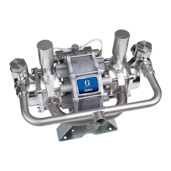
Instructions–Parts List
STAINLESS STEEL OR CARBON STEEL
Air–Powered Gluttonr
Pumps
100 psi (0.7 MPa, 7 bar) Maximum Incoming Air Pressure
400 Series Pumps
400 psi (2.8 MPa, 28 bar) Maximum Fluid Working Pressure
Model 220663, Series D
Model 237008, Series A
Carbon steel pumps*
Model 220666, Series D
Model 237011, Series A
Stainless steel pumps*
Electro-polished for use with waterborne coatings
1200 Series Pumps
1200 psi (8 MPa, 83 bar) Maximum
Fluid Working Pressure
Model 220664, Series D
Model 237009, Series A
Carbon steel pumps*
Model 220667, Series D
Model 237012, Series A
Stainless steel pumps*
Electro-polished for use with waterborne coatings
2500 Series Pumps
2500 psi (17 MPa, 170 bar) Maximum Fluid
Working Pressure
Model 220665, Series D
Model 237010, Series A
Carbon steel pumps*
Model 220668, Series D
Model 237013, Series A
Stainless steel pumps*
Electro-polished for use with waterborne coatings
*See TECHNICAL DATA on pages 44 through 46
for a complete materials list.
Important Safety Instructions
Read all warnings and instructions in this manual.
Save these instructions.
307843ZAF
EN
Advertisement
Table of Contents

Related Manuals for Graco Glutton 400 Series


Summary of Contents for Graco Glutton 400 Series
- Page 1 Instructions–Parts List STAINLESS STEEL OR CARBON STEEL Air–Powered Gluttonr Pumps 307843ZAF 100 psi (0.7 MPa, 7 bar) Maximum Incoming Air Pressure 400 Series Pumps 400 psi (2.8 MPa, 28 bar) Maximum Fluid Working Pressure Model 220663, Series D Model 237008, Series A Carbon steel pumps* Model 220666, Series D Model 237011, Series A...
-
Page 2: Table Of Contents
................Graco Standard Warranty . -
Page 3: Warnings
D Use only Graco approved hoses. Do not remove the spring guard that is used to help protect the hose from rupture caused by kinks or bends near the couplings. - Page 4 D This equipment is for professional use only. D Read all instruction manuals, tags, and labels before operating the equipment. D Use the equipment only for its intended purpose. If you are uncertain about usage, call your Graco distributor. D Do not alter or modify this equipment. Use only genuine Graco parts and accessories.
- Page 5 WARNING FIRE AND EXPLOSION HAZARD Improper grounding, poor ventilation, open flames, or sparks can cause a hazardous condition and result in a fire or explosion and serious injury. D Ground the equipment and the object being sprayed. See Grounding on page 7. D Proper hose grounding continuity is essential in maintaining a grounded spray/dispense system.
-
Page 6: Installation
Con- with the accumulators in the top position as shown tact your Graco distributor for assistance in plan- in Fig. 1. The accumulators must be in the position ning a system to suit your needs. - Page 7 Installation D Air Compressor: Follow the manufacturer’s recom- Grounding mendations. WARNING D Spray gun or dispensing valve: Obtain grounding This pump must be grounded. The steps for through connection to a properly grounded fluid grounding may differ from the way you ground hose and pump.
- Page 8 Installation Connect the Fluid Lines 3. Install a control device, such as a gun, dispensing valve, or shutoff valve, on the grounded fluid 1. Use grounded fluid hoses. hose (H). a. The pump fluid outlet (J) on the 400 and Connect the Fluid Suction Line 1200 Series Pumps is 1 npt(f) .
- Page 9 Installation Connect the Air Lines 6. Install one bleed-type master air valve (C) down- stream from the air regulator and use it to relieve trapped air. Locate the other master air valve up- 1. Install the air line accessories to the left of the stream from all air line accessories and use it to pump as shown in Fig.
-
Page 10: Operation
Operation Pressure Relief Procedure Start and Adjust the Pump NOTE: Check all fittings to be sure they are tight. Be WARNING sure to use a thread sealant compatible with the fluid being pumped on all male pipe threads. The system pressure must be manually relieved to prevent the system from starting or spraying acci- 1. - Page 11 Operation 7. If you are flushing: CAUTION a. Run the pump long enough to thoroughly clean the pump and hoses. Never allow the pump to run dry of fluid. A dry pump b. Close the fluid control device and air regulator will accelerate to a high speed, possibly damaging (D).
-
Page 12: Troubleshooting
Troubleshooting Relieve the pressure, and check all probable causes WARNING before disassembling the pump. PRESSURIZED EQUIPMENT HAZARD To reduce the risk of a serious injury whenever you are instructed to relieve pressure, follow the Pres- sure Relief Procedure on page 10. SYMPTOM PROBABLE CAUSE TEST PROCEDURE... - Page 13 Troubleshooting SYMPTOM PROBABLE CAUSE TEST PROCEDURE REMEDY 3. Pump runs but a. Air in fluid line a. Check for spitting at a. Bleed fluid line until con- does not main- fluid line outlet stant flow is tain constant obtained pressure b.
-
Page 14: Maintenance
Maintenance Flush the Pump With Compatible Solvent Tighten Threaded Connections WARNING 1. Before each use, check all hoses for wear or dam- age and replace as necessary. Be sure all To reduce the risk of fluid injection injury, static threaded connections are tight, and leak-free. sparking and splashing, read and follow Flushing Safety under FIRE OR EXPLOSION HAZARD on page 5. -
Page 15: Service
Service Repairing the Ball Check Valves Disassembly NOTE: Parts marked with an asterisk are included in a 1. Relieve the pressure. repair kit, for example, (54*). See pages 38 and 39 for repair kit part numbers. Use all the parts in the kit for the best results. - Page 16 Service Assembly 6. Apply 10 psi air to move the piston to one side and hold it there. Replace the o–ring (18*) in the 1. Slide the retaining plate (20), bellows (14*), and groove in the tapered side of the retaining plate intake housing (36) onto the piston shaft (15).
- Page 17 Service 46 or 61 NOTES: Lubricate threads. Torque to 55 to 85 ft-lb (75 to 115 NSm) Fit o-ring into groove 400 & 1200 Series pumps: Torque to 40 to 50 ft-lb (54 to 68 NSm) 2500 Series pumps: Torque to 35 to 40 ft-lb (47 to 54 NSm) 223111 &...
- Page 18 Service Repairing the Air Motor and Piston Assembly NOTE: Parts marked with an asterisk are included in a 1. Apply lithium base grease to all packings, seals, repair kit, for example, (23*). See pages 38 and 39 for and the inside of the air motor cylinder (27) before repair kit part numbers.
- Page 19 Service NOTES: Take care not damage tubes when re- moving cap (25) Apply high-strength sealant to threads Torque to 7.4 to 12.5 ft-lb (10 to 17 NSm) Press fit to flush Press fit to bottom 02327 Fig. 7 307843...
- Page 20 Service Repairing the Air Control Valve 5. Thread one spool (40c) onto the stem (40d) and insert it into the center housing (40a); be careful NOTE: Air Valve and Pilot Valve Repair Kit 220656 is not to dislodge the u-cups (40j) and retainers available.
- Page 21 Service 40h REF 40p REF 40h* *40j *40i NOTES: Torque to 2.2 to 3.7 ft-lb (3 to 5 NSm) Press fit using 40 to 60 lb (18 to 27 kg) force *40h Lubricate with lithium-base grease *40f *40g Apply medium strength sealant to threads. Torque to 0.58 to 1.1 ft-lb (0.79 to 1.47 NSm) Apply sealant to threads...
- Page 22 Service Repairing the Pilot Valve Assembly NOTE: Air Valve and Pilot Valve Repair Kit 220656 is 1. Apply lithium base grease to the inside and outside available. See page 38 to order. Parts included in the of the air valve (5b), and to the o-rings and seals. kit are marked with an asterisk, for example, (5j*).
- Page 23 Service NOTES: Torque to 7.4 to 12.5 ft-lb (10 to 17 NSm). Torque to 2.2 to 3.7 ft-lb (3 to 5 NSm). Lubricate with lithium-base grease. 02329 Fig. 9 307843...
- Page 24 Parts 400 Series Carbon Steel Pumps Model 220663, Series D Model 237008, Series A 02332 24 307843...
- Page 25 Parts 400 Series Carbon Steel Pumps Ref. Part No. Description Qty. Model 220663, Series D Model 237008, Series A 183097 CYLINDER, air motor Ref. 107160 QUAD RING; buna-N Part No. Description Qty. 183355 PISTON, air motor 108712 NUT, hex; M8 x 1.25 183229 STUD 104572...
-
Page 26: 400 Series Stainless Steel Pumps, Models 220666 And 237011
Parts 400 Series Stainless Steel Pumps Model 220666, Series D Model 237011, Series A 02332 26 307843... - Page 27 Parts 400 Series Stainless Steel Pumps Ref. Part No. Description Qty. Model 220666, Series D Model 237011, Series A 183097 CYLINDER, air motor Ref. 107160 QUAD RING; buna-N Part No. Description Qty. 183355 PISTON, air motor 108712 NUT, hex; M8 x 1.25 183229 STUD 104572...
-
Page 28: 1200 Series Carbon Steel Pumps, Models 220664 And 237009
Parts 1200 Series Carbon Steel Pumps Model 220664, Series D Model 237009, Series A 02332 28 307843... - Page 29 Parts 1200 Series Carbon Steel Pumps Ref. Part No. Description Qty. Model 220664, Series D Model 237009, Series A 108874 O-RING; buna-N 183097 CYLINDER, air motor Ref. Part No. Description Qty. 107160 QUAD RING; buna-N 183355 PISTON, air motor 108712 NUT, hex;...
-
Page 30: 1200 Series Stainless Steel Pumps, Models 220667 And 237012
Parts 1200 Series Stainless Steel Pumps Model 220667, Series D Model 237012, Series A 02332 30 307843... - Page 31 Parts 1200 Series Stainless Steel Pumps Ref. Part No. Description Qty. Model 220667, Series D Model 237012, Series A 183097 CYLINDER, air motor Ref . 107160 QUAD RING; buna-N Part No. Description 183355 PISTON, air motor 108712 NUT, hex; M8 x 1.25 183229 STUD 104572...
-
Page 32: 2500 Series Carbon Steel Pumps, Models 220665 And 237010
Parts 2500 Series Carbon Steel Pumps Model 220665, Series D Model 237010, Series A 02334 32 307843... - Page 33 Parts 2500 Series Carbon Steel Pumps 108874 O-RING; buna-N 183097 CYLINDER, air motor Model 220665, Series D Model 237010, Series A 107160 QUAD RING; buna-N 183355 PISTON, air motor 183229 STUD Part No. Description 108768 SCREW, cap, hex hd; 108712 NUT, hex;...
-
Page 34: 2500 Series Stainless Steel Pumps, Models 220668 And 237013
Parts 2500 Series Stainless Steel Pumps Model 220668, Series D Model 237013, Series A 02335 34 307843... - Page 35 Parts 2500 Series Stainless Steel Pumps Model 220668, Series D Model 237013, Series A Ref. Ref. Part No. Description Qty. Part No. Description 108712 NUT, hex; M8 x 1.25 183097 CYLINDER, air motor 107160 QUAD RING; buna-N 104572 WASHER, spring lock 183355 PISTON, air motor 108786...
-
Page 36: Air Control Valve 220902
Parts Ref No. 40 Air Control Valve 220902 NOTE: This assembly is included with all pump models. 40h* *40j *40i *40h *40f *40g 02330 Ref. Ref. Part No. Description Qty. Part No. Description Qty. 108780 SCREW, cap, hex hd; 183370 HOUSING, valve center M5 x 0.8 x 150 183369... -
Page 37: Pilot Valve 221133
Parts Ref No. 5 Pilot Valve 221133 NOTE: This assembly is included with all pump models. 02331 Ref. Ref. Part No. Description Qty. Part No. Description Qty. 108383 FITTING, barbed, buna-N o-ring 183604 STEM, valve seal; 10–32 UNF–2A 183603 VALVE, air 156766 GASKET, copper 183605... -
Page 38: Repair And Conversion Kits
Repair and Conversion Kits The reference numbers shown in the kits below correspond to the reference numbers used in the parts lists and drawings on pages 24 to 37. Use all the kit parts, even if the old parts still look good. Standard Air Valve and Pilot Valve Repair Kit 400 Series Optional Pump Repair Kit 24C134, with 220656... - Page 39 Repair and Conversion Kits The reference numbers shown in the kits below correspond to the reference numbers used in the parts lists and drawings on pages 24 to 37. Use all the kit parts, even if the old parts still look good. 400 and 1200 Series Pumps Carbide Ball and Seat 1200 Series Standard Pump Repair Kit 237017 Conversion Kit 221134...
- Page 40 Repair and Conversion Kits The reference numbers shown in the kits below correspond to the reference numbers used in the parts lists and drawings on pages 24 to 37. Use all the kit parts, even if the old parts still look good. 2500 Series Standard Pump Repair Kit 220950 2500 Series Standard Pump Repair Kit 237016 (for pump Models 220665 and 220668)
-
Page 41: Filter, Regulator, Lubricator Kit 222345
Filter, Regulator, Lubricator Kit Filter, Regulator, Lubricator (FRL) Kit 222345 FRL Kit 222345 (shown below) is available for Glutton pumps. Ref. Ref. Part No. Description Qty. Part No. Description Qty. 223004 Filter, Regulator Lubricator Assy 101689 GAUGE, Air Pressure Includes items 1 to 7 183746 Bracket 106149... -
Page 42: Drum Cover Kit 222655
Drum Cover Kit and Return Tube Kit Drum Cover Kit 222655 Return Tube Kit 223319 Drum Cover Kit 222655 (shown below with a Glutton Return Tube Kit 223319 (shown below) is available. pump) is available. Ref. Part No. Description Qty. Ref. -
Page 43: Suction Kit 208259
Suction Kit Suction Kit 208259 55 gallon drum size Suction Kit 208259 (shown below) is available. Ä Ä Ä Ä Ref. Part No. Description Qty. 156589 UNION, 90_ adapter, 3/4 nptf x 3/4 npsm 214961 HOSE, cpld, nylon, 3/4 in. ID, 6 ft (1.8 m) long, w/spring guard 156591 ELBOW, 90_... -
Page 44: 400 Series Pumps
Technical Data, 400 Series Pumps Maximum working pressure ....400 psi Wetted Parts: (2.8 MPa, 28 bar) Model 220663 and 237008: carbon steel, stainless steel, polypropylene, ultra Maximum air input pressure . -
Page 45: 1200 Series Pumps
Technical Data, 1200 Series Pumps Maximum working pressure ....1200 psi Wetted Parts: (8.3 MPa, 83 bar) Model 220664 and 237009: carbon steel, stainless steel, polypropylene, ultra Maximum air input pressure . -
Page 46: 2500 Series Pumps
Technical Data, 2500 Series Pumps Maximum working pressure ....2500 psi Wetted Parts: (17 MPa, 170 bar) Model 220665 and 237010: carbon steel, stainless steel, polypropylene, ultra Maximum air input pressure . -
Page 47: Dimensional Drawing
Dimensional Drawing 02321 Height 400 and 1200 Series pumps: 15.1 in. (384 mm) 2500 Series pumps: 12.6 in. (320 mm) Width: 19.6 in. (498 mm) Depth: 15.83 in. (401 mm) Air inlet 1/2 npt(f) Fluid inlet: 1.25 npt(f) Fluid outlet 400 and 1200 Series pumps: 1 npt(f) 2500 Series pumps: 3/4 npt(f) Mounting Hole Layout... -
Page 48: Graco Standard Warranty
With the exception of any special, extended, or limited warranty published by Graco, Graco will, for a period of twelve months from the date of sale, repair or replace any part of the equipment determined by Graco to be defective.
Need help?
Do you have a question about the Glutton 400 Series and is the answer not in the manual?
Questions and answers