
Subscribe to Our Youtube Channel
Related Manuals for Charlton & Jenrick Opulus 16


Summary of Contents for Charlton & Jenrick Opulus 16
- Page 1 Best of British fires, fireplaces & stoves Installation & Operation Manual Opulus 16 Electric Fire Real Flame Technology Please read the instructions carefully before installation and keep, for future reference.
-
Page 3: Table Of Contents
CONTENTS Important Safety Information ..............1 Technical Specifications ..............3 Parts And Hardware ................4 Appliance Dimensions ................5 Installation Instructions ............... 6 Operating Instructions ................11 Manual Control Panel ..............12 Remote Control ..............13 APP Control ................17 Maintenance .................. -
Page 4: Important Safety Information
1. IMPORTANT SAFETY INFORMATION Read these instructions carefully before using the appliance. For indoor use only. This appliance is not suitable for use outside the house and only suitable for well insulated spaces or occasional use. Do not use this appliance in the immediate surroundings of ... - Page 5 This appliance is not intended for use by persons (including children) with reduced physical, sensory, or mental capabilities, or lack of experience and knowledge, unless they have been given supervision or instruction concerning use of the appliance by a person responsible for their safety.
-
Page 6: Technical Specifications
2. TECHNICAL SPECIFICATIONS Model No.: Opulus 16 Supply Voltage: AC 220-240 V 50 Hz Maximum power consumption: 1500W Power for flame and fuel bed effect: 65 W Power for mood light: 9 W Heat Output: Nominal heat output (Pnom): 1500 W Minimum... -
Page 7: Parts And Hardware
3. PARTS AND HARDWARE 3.1 Unpack the fire carefully and make sure that the appliance is intact with no signs of damage caused by transport and no part has been exposed to water. If in doubt, do not use the appliance and contact your retailer. -
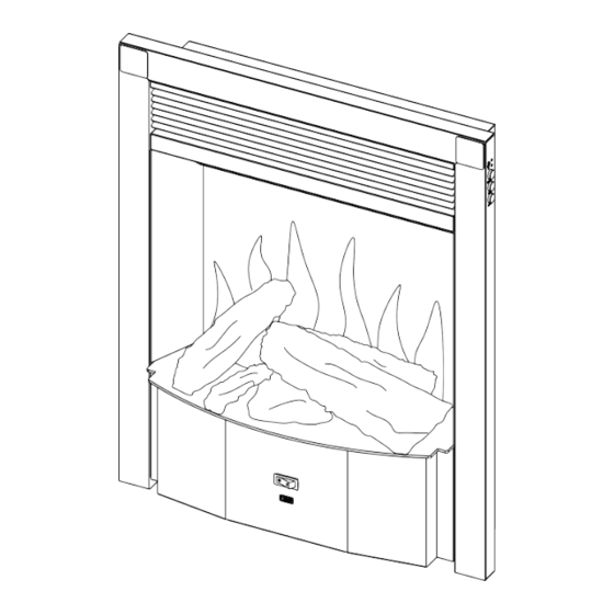
Page 8: Appliance Dimensions
Fuel Bed Plate(1pc) Power Cord EU (1pc) AAA Battery (2pcs) Remote (1pc) Quick Guide Manual (1pc) Instruction Manual (1pc) 4. APPLIANCE DIMENSIONS Unit:mm... -
Page 9: Installation Instructions
5. INSTALLATION INSTRUCTIONS 5.1 PREPARATION BEFORE INSTALLATION TOOLS REQUIRED A screwdriver, a spirit level and drill will be needed. LOCATE THE APPLIANCE Your new electric fireplace may be installed virtually anywhere in your home. However, when choosing a location, ensure that the general instructions are followed: For the best result, install out of direct sunlight, water or very damp air. - Page 10 CONNECT MOOD LIGHTS CABLE The interface of the mood lights cable is positioned close to the power cord. Please also check the operation of the mood lights after connecting. Note: Compatible mood lighting devices are available from Charlton & Jenrick Ltd., Other brands may not be suitable and void the warranty.
- Page 11 Insert the wall plugs (for masonry wall only). Screw four ST5*25 screws into the wall, leaving 2mm projection. Push the firebox into the opening and lock it on to the screws. keyhole slots 5.3 FIT THE FASCIA AND FRET Note: A fascia, trim or fret isn’t included with the appliance.
- Page 12 Put the magnets (packed with the fascia or trim) onto the rear of the fascia or trim, two magnets on each side and attach the fascia or trim to the appliance. Note: If the appliance to be fitted with the Elite or Prestige Fascia, please replace the fuel bed plate with the larger fuel plate marked “A”...
- Page 13 5.4 FUEL BED ARRANGEMENT There are two fuel bed arrangements for you to choose: A. Decorative Log Set Arrangement Fit the LED strip into the log with slot and then connect the cable to the fuel bed. Freely arrange other logs and when you are happy with the layout, carefully scatter the glass embers around all the logs, ensuring that all visible areas of the fuel bed, including underneath and behind the logs, are covered.
-
Page 14: Operating Instructions
6. OPERATING INSTRUCTIONS WARNING! Do not operate the appliance if it is damaged or malfunctions. If you suspect the appliance is damaged or malfunctions, call a qualified service engineer to inspect the appliance, and replace any part of the electrical system, if necessary, before reusing. -
Page 15: Manual Control Panel
THE BOOT PROCESS FOR FLAME EFFECT Switch on the appliance by MAIN SWITCH, then press “STAND-BY” button on the appliance. The fuel bed starts to blink and the screen displays “WELCOME”. The booting process will take about 30 seconds and the flame effect will be turned on. If you turn off the flame effect using the STANDBY button, the flame effect will remain dormant for 20 minutes, after that you can turn on the flame immediately. -
Page 16: Remote Control
6B. REMOTE CONTROL NOTE: The start-up time of the screen is 30 seconds, during this period, “WELCOME” is displayed on the screen, the fuel bed starts to flash, and the appliance cannot be operated. After that, the fuel bed stops flashing, the flame will be turned on, and the appliance can be operated normally. - Page 17 NOTE: The remote control handset must be left in the same room as the appliance because it houses the thermostat that regulates heat output. Also, when using the APP, the remote must also be in the same room and have batteries fitted and working to ensure accurate temperature control. Remote Control Set up.
- Page 18 Press the ' ' and ' ' button to select the 5 levels of brightness. Down Light/Ambient Light Note: If mood lights are not connected, please ensure the brightness is set to zero. Press once until shows on the screen to enter the down light setting mode. Press the ' ' and ' ' button to select 2 different down light colours and OFF...
- Page 19 Window Open Detection When the transmitter detects a rapid drop in room temperature, it will be judged as a window open, the warning icon will be displayed, and the heater will be turned off automatically. After the indoor temperature has risen or a manual override of the warning (by operating remote control) has been done, the fire will return to normal working state.
-
Page 20: App Control
6C. APP Control Visit your APP store for IOS or Android to download the C&JsmartFIRE APP. Or use the QR code below. Follow your devices onscreen instructions to create an account. Once installed, follow the procedure below to pair the device with your appliance. -
Page 21: Maintenance
7. MAINTENANCE WARNING: Before any maintenance or cleaning of the exterior of the appliance, the unit should be disconnected from the power supply, remove supply plug from power socket or turn off and remove fuse from fused spur, wait until the appliance is cool. -
Page 22: Service Parts List
8. SERVICE PARTS LIST Item Part Number LED Model 1 Rear Screen 9760 2 LCD Screen 9761 3a Fuel Bed Shelf “A” not fitted 9762 3b Fuel Bed Shelf “B” fitted 9763 4 Remote Control 9727 5 Speaker 8888 6 LCD Driver Board 9764 7 Down Light 9765... -
Page 23: Others
9. OTHERS Environment Meaning of crossed –out wheeled dustbin: Electrical appliances should not be disposed of as unsorted municipal waste. Separate collection facilities should be used in the disposal of electrical appliances. Contact your local government for information about the available collection systems. If electrical appliances are disposed of in landfills or dumps, hazardous substances can leak into the groundwater and get into the food chain, damaging your health and well-being. - Page 24 Charlton & Jenrick Ltd Unit D, Stafford Park 2, Telford, Shropshire, TF3 3AR Fax :+44 1952 200 480 Tel: +44 1952 200 444 www.charltonandjenrick.co.uk...
Need help?
Do you have a question about the Opulus 16 and is the answer not in the manual?
Questions and answers